In recent years, the automatic identification method has been rapidly developed in the fields of service, goods sales, logistics distribution, commerce, production enterprises and material circulation, and the radio frequency identification technology has developed rapidly and has gradually become an independent interdisciplinary. The professional fields include high frequency technology, semiconductor technology, electromagnetic compatibility technology, data security technology, telecommunications and manufacturing technology. The antenna as a key component of the design of the radio frequency identification system directly affects the performance of the system.
1 Principle of radio frequency identification systemRadio Frequency Identification (RFID) systems typically consist of a reader (PCD) and a transponder (PICC). A typical reader consists of a high frequency module (transmitter and receiver), a control unit and a coupling element [1] connected to the transponder. The transponder is the true data carrier of the RFID system. Typically, the transponder consists of a coupling element and a microelectronic chip. The transponder does not have its own independent power supply, but receives RF power from the reader within the response range of the reader. The energy required for the operation of the transponder, like clock pulses and data, is obtained by non-contact transmission of the coupling unit [2]. Therefore, the coupling element, the antenna, plays a key role in the system. The design of the antenna is directly related to the communication distance of the system and the reliability of data transmission. The following is mainly to take the radio frequency base station chip U2270B as an example to discuss the antenna design of the radio frequency identification system.
There are two LC circuits in the RFID system: an LRCR circuit consisting of a base station coil and a connection capacitor, and an LTCT circuit consisting of a transponder coil and a connection capacitor. In a single coil system, two LC circuits are required to be tuned to the same resonant frequency. If the resonant frequencies of the base station and the transponder do not match, zero modulation is generated, which degrades the performance of the system. After the system is designed and formed, the inductance of the antenna is fixed. Therefore, to change the resonant frequency of the LC circuit, only the capacitance in the loop is adjusted.
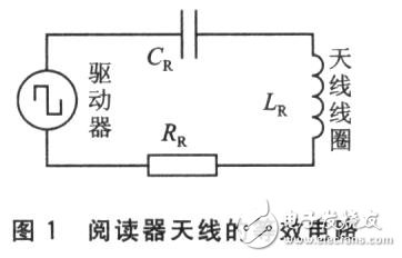
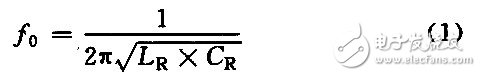
The reader base station antenna is a series resonant circuit composed of an inductor, a capacitor and a resistor, as shown in FIG. Its characteristics are expressed by the resonant frequency fo and the Q factor [3]. Fo is the operating frequency of the RFID system, which is determined by the inductance and capacitance of the antenna. It can be calculated by equation (1):
The general design uses a reader to operate in a single frequency mode, which is available for the U2270B, fo=125 kHz. The relationship between the Q factor (QR) and the bandwidth B of the antenna and the resonant frequency fo is B = fo / QR. A high QR value results in a higher reader antenna voltage, which increases the energy delivered to the transponder. The disadvantage of the high QR value is that the antenna bandwidth is reduced, and the data signal voltage induced by the transponder is reduced when the transponder frequency is shifted, which makes the demodulation of the radio frequency card difficult [4] and cannot work normally. The coupling factor is the coupling between the electromagnetic field generating coil and the transponder coil of the reader base station. The coupling factor depends on the structural parameters of the system and directly affects the reading distance between the reader and the transponder. Optimizing the coupling factor will be beneficial to the energy transfer channel and the signal transmission channel. To determine the coupling factor, the test response coil (TTC) and circuitry provided by Temic can be used for testing. The value range of QR should be controlled from 5 to 15, generally taking QR= 12, which can be suitable for most application situations. If the inductance of the antenna is determined, then the QR factor can be adjusted by the RR by equation (2):

The antenna design is mainly based on the actual requirements to determine the mechanical size of the antenna, the number of turns of the coil, the inductance and the capacitance of the equivalent circuit, so that the antenna has the highest working efficiency. The general steps of the antenna design are described below.
2.1 Optimizing the magnetic field coupling factor
The coupling factor is only related to the mechanical dimensions of the coil arrangement (eg coil diameter, reading distance, coil azimuth) and the material in the vicinity of the coil in the magnetic field, independent of the inductance of the reader antenna or transponder antenna. In order to increase the coupling factor, the transmission distance should be as small as possible, and the antenna axes of the reader and transponder should be parallel. If the reading distance is determined, the reader antenna coil diameter and the magnetic field coupling factor k can be optimally designed according to this particular distance. The magnetic field strength can be calculated by equation (3):
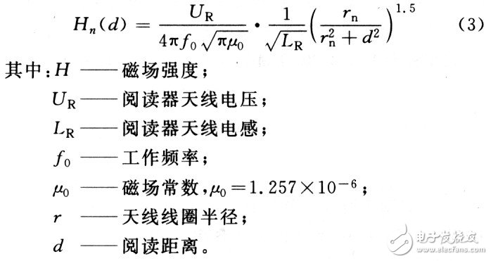
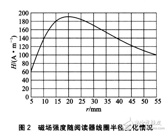
According to equation (3), the magnetic field strength has a direct relationship with the antenna structure, and the magnetic field coupling factor k also depends on the structural size of the coil arrangement, so the magnetic field strength is also proportional to k. Optimizing the coupling factor is to determine the relationship between the antenna radius and the reading distance when the antenna efficiency is highest. Figure 2 shows the magnetic field strength as a function of coil radius under certain conditions. The measurement conditions of Fig. 2 are: fo = 125 kHz, LR = 737 μH, r = 5 to 55 mm, and d = 20 mm.
As can be seen from Figure 2, if the reading distance d is constant, when rd, the field strength is substantially proportionally reduced. It can be concluded that the optimal radius of the antenna coil is r≈d. & lt;/p
2.2 Determination of the coupling factor of the magnetic field
In order to determine the coupling factor, the test response coil (TTC) and circuit provided by Temic can be used for testing. The test principle is shown in Figure 3. The TTC can be placed in the position of the actual transponder. When the reader antenna is activated by the signal generator, the voltage UT through the TTC can be measured.
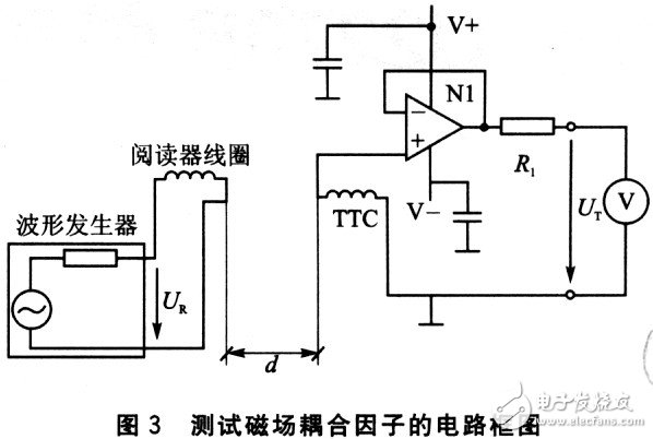
Figure 4 is an equivalent circuit model of the TTC connected to the measuring device.
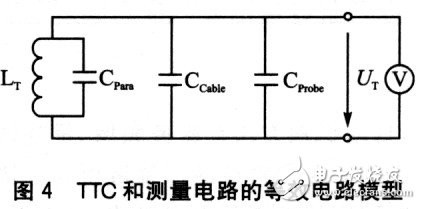
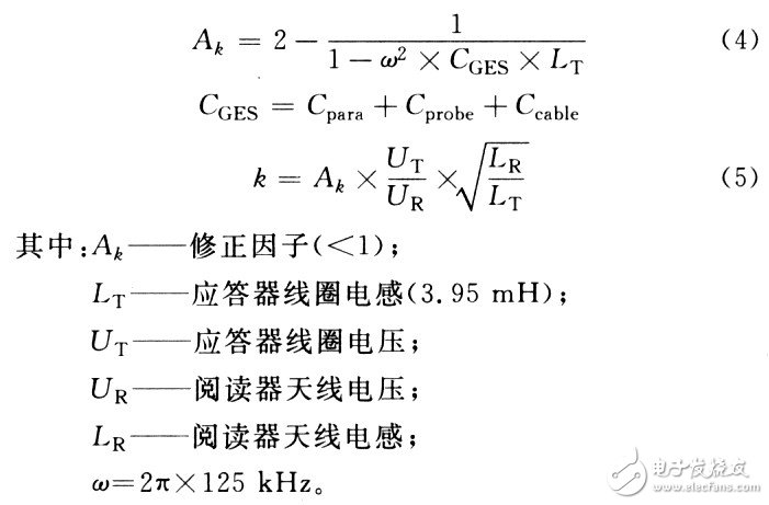
Cpara is the internal parasitic capacitance of the coil, and Ccable and Cprobe are the cable capacitance and load capacitance of the measuring device. These capacitors have an effect on the measured voltage. In order to make the measurement effect more accurate, the correction factor Ak is introduced here, and the calculation formula is as follows:
Click to see the original picture
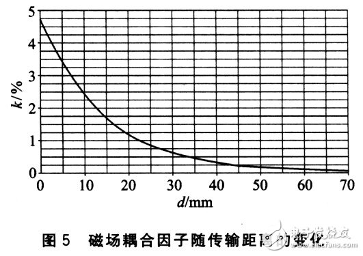
Figure 5 shows the results of the measured coupling factors in the case of different reading distances.
2.3 How to meet the actual frequency tolerance
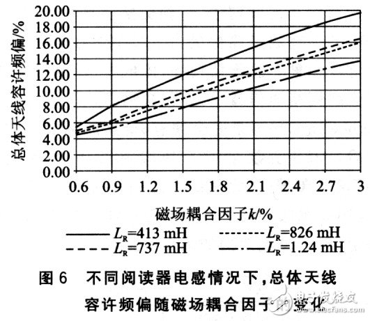
Figure 6 is a plot of the total antenna allowable frequency offset as a function of the magnetic field coupling factor k when the operating frequency is fixed and the reader inductance is at a different value. As can be seen from Fig. 6, the overall allowable frequency offset increases with an increase of k, and decreases as the inductance of the reader coil increases. It is worth noting that the antenna inductance is inversely proportional to the current flowing through the antenna. For the U2270B, the maximum antenna current (IRpp) is limited to 400 mA. If the voltage of the reader antenna coil is taken into account, the inductance LR of the antenna cannot be less than 413 μH. In Figure 6, the total antenna of the ordinate allows the frequency offset and the abscissa magnetic field coupling factor to correspond to a point, and any inductance value greater than 413/μH and less than the inductance corresponding to the nearest curve above the corresponding point can be selected. After the LR is determined, the antenna capacitance can be calculated by the equation (6) when the operating frequency is fixed:
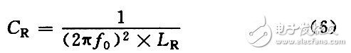
Where fo≈125 kHz.
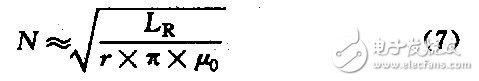
The number of turns of the antenna coil can be calculated by equation (7):
If the conditions are as follows:
The allowable frequency offset of the reader coil is ±3%; the transmissible frequency offset of the transponder coil is ±4%; the nominal reading distance is 20 mm.
Step 1: In order to optimize the magnetic field coupling effect, the reader coil radius is chosen to be r=20mm.
& nbsp; Step 2: According to Figure 5, the coupling factor k = 1.2% can be determined.
Step 3: Calculate the total frequency allowable frequency offset to be ± 3% and ± 4% of the sum ± 7%. As can be seen from Figure 6, only the curve with LR = 1.24 mH is at the point (k = 1.2%). , under ±7%), so LR can take any value between 413μH and 850μH. Here LR = 737 μH. The number of turns of the coil N=97 can be calculated by the formula (7), and CR=2.2 nF can be calculated by the formula (6).
Conclusion
This paper mainly analyzes the general steps of antenna design for RFID systems for U2270B. Factors such as external disturbances may also bring some special problems to the design process. This article only hopes to provide some inspiration for radio frequency identification system research.
It is used for continuous level measurement. The signal transmitted by its sensor is collected by the receiving system after being reflected by the target, and the distance of the target is determined by measuring the reflection running time. Then the level distance is converted into an output signal and output as a measured value.
The liquid level radar is applicable to the continuous non-contact liquid level measurement of liquid cargo tanks and overflow tanks of oil tankers and chemical carriers. It is also applicable to the liquid level monitoring of other oil tanks, towers, tank equipment and oil production platforms. Its measurement results are not affected by medium replacement, temperature change and gas or steam coverage.
Radar Level Gauge Sensor,Level Gauge Sensor,Level Sensor Durable,Durable Radar Level Gauge Sensor
Taizhou Jiabo Instrument Technology Co., Ltd. , https://www.jbcbyq.com