Abstract: In view of the inconvenient reading of mercury thermometer, slow response speed and narrow surface in ordinary households, the design scheme of digital speech thermometer is proposed. The DS18B20 in stainless steel is used as the temperature sensor, the ISD1720 is used for voice recording and playback, and the STC89C52 single-chip microcomputer is used for temperature signal acquisition, data processing and voice playback control to construct the actual circuit system. Experiments show that the digital voice thermometer has a measurement range of 0 to 99.9 ° C, a display resolution of 0.1 ° C, an error of no more than ± 0.5 ° C, a fast temperature measurement, convenient reading, clear voice, and voice broadcast interval. Adjustable, it can be widely used in homes or where voice prompts are required.
Key words: digital voice thermometer; temperature sensor; temperature signal acquisition; data processing
This article refers to the address: http://
0 Introduction Temperature measurement plays an important role in people's daily life. When people feel uncomfortable, they usually need to measure body temperature; the baby in the house or the liquid food eaten by the patient, the bath water prepared for the baby, etc., need to feel in advance. Measuring the temperature, if the temperature is too high or too low, will cause harm to the patient or the baby. At present, the cheap thermometer is widely used at home, but it is usually only used to measure body temperature, the range is small, the maximum is 42 °C; the reading is inconvenient, especially the elderly have poor eyesight, it is not easy to read accurately; it is inconvenient to measure outside the body temperature. Use, and mercury leakage after damage to the body will cause harm, etc., some countries have begun to ban the sale of mercury thermometers; non-contact infrared thermometers are convenient to use, but expensive. The literature introduces a digital thermometer design method for industrial applications. The literature introduces the method of designing a thermometer using a single-chip computer with voice processing function and a voice chip, but in the miniaturization of the instrument,
Under the influence of ease of use and cost, it is not easy to promote in general households, and its core technology is not disclosed. Therefore, it is of great practical value to develop a temperature measuring instrument which is convenient to use, can display digitally and has voice prompts, is inexpensive, and has a wide range of applications, and is particularly suitable for home use.
1 system design
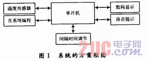
1.1 Working principle of the system The single-chip computer collects the signal of the temperature sensor. The collected data is output to the digital tube for display after processing, and is output to the voice module for voice temperature prompting. The dial switch is used for setting, and the voice function can also be turned off. The system block diagram is shown in Figure 1.

1.2 system hardware design
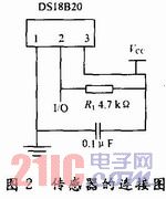
1.2.1 The temperature sensor adopts the digital temperature sensor DS18B20. This product adopts the networkable digital temperature sensor chip produced by American DALLAS Company. It is small in size, easy to use, and has various package forms. It is suitable for digital temperature measurement and control in various narrow spaces. Field; Because the project requires measurement of liquid temperature, convenient human contact, etc., it is packaged with stainless steel protection tube, which has the functions of wear resistance, collision resistance and waterproof. The DS18B20 can realize two-way communication only when it is connected to the microprocessor. It can measure temperature range from -55 to +125 °C, programmable to 9 to 12 bits of A/D conversion accuracy, and temperature resolution is up to 0.062 5 ° C. The measured temperature is serially output in a 16-bit digital way with symbol expansion; its working power can be generated either at the far end or by parasitic power supply; multiple DS18B20s can be connected in parallel to 3 or 2 lines, CPU only A port line is required to communicate with many DS18B20s, which occupy fewer microprocessor ports and save a lot of leads and logic circuits; the connection circuit is shown in Figure 2:

In Figure 2, the 2 pin of the sensor is connected to the input/output (I/O) pin of the microcontroller, and the two sides communicate with each other, using a 4.7 kΩ resistor pull-up. Since the DS18B20 single-line communication function is completed in a time-sharing manner, the system must strictly follow the protocol for its operations. The operation protocol is: initialize DS18B20 (send reset pulse) → send ROM function command → send memory operation command → process data, all operations have strict timing requirements.
1.2.2 MCU is compatible with MCS51
STC89C52, with 8K bytes of in-system programmable Flash memory, its MOSI, MISO, REST, SCK and other pins are connected to the parallel port of the computer by latching, which can realize the internal Flash memory programming, including 512 B RAM, 32 programmable I/O lines, and three 16-bit timers/counters provide a highly flexible and ultra-efficient solution for many embedded control applications, making them ideal for this project.
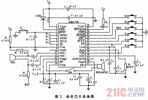
1.2.3 The voice module adopts the highly integrated and high-performance ISD1720 voice recording and playback chip produced by American Huabang Company. The sampling rate is adjusted between 4 and 12 kHz. According to the sampling frequency, 12~36 s can be recorded. The voice information, the voice information is stored in the solid multi-level memory array inside the chip, and can be accurately addressed by the 11-bit address in the instruction; the chip sets the voice processing and storage in one, has repeated self-development, power down Information storage, can work in independent button mode and SPI control mode, automatically enter low power state at the end of recording and playback, can be directly microphone input or analog channel input, or directly output by speaker, chip working voltage 2.4 ~ 5.5 V In the case of multiple recordings, the basic memory unit entry address range is 0X010~0X09F. The application circuit is shown in Figure 3. According to the need, the recorded voice is divided into 13 segments, namely “zero to ten, point, degreeâ€, such as 37.5 degrees, and the broadcast is “three, ten, seven, five, five, degreesâ€, and each voice is recorded. The time is about 1.35 s. Since the recording time is not easy to accurately grasp, the 13-segment voice is recorded by manual control, and then each voice recording effect is manually checked. As shown in FIG. 3, the S4 is closed for voice information recording, and loose. The recording is finished at the end, the voice information is entered through the MIC, and the S5 key is triggered to play, and the effect of the currently recorded information segment is checked. During the recording or playing process, the progress of the operation can be understood by flashing the LED; if a certain voice recording effect is obtained Not ideal, it must be deleted in time, because in the manual control mode, the delete operation is only valid for the beginning and last information; after the recording is completed, it must also check whether each piece of information is stored in the ring structure in the storage system of the device. This can be achieved by closing S5 and holding it. At this point, the device will play all the pieces of information between the current segment and its previous segment in sequence. By repeating the recording until it is satisfied; of course, it can also be implemented using a commercial recording device.
According to the range of voice storage addresses inside the chip, each segment of voice stores about 11 lines. In order to accurately know the entry address and end address of each voice, it can be checked by the single chip microcomputer. ISD1720 provides 4-wire (SCLK, MOSI, MISO, SS) SPI interface and MCU connection. Because the SPI timing of the two is not easy to coordinate, the system adopts P1.1, P1.2, P1.3, P1.4 of MCU. The analog SPI timing controls the ISD1720. During the specific operation, after the device initialization is completed, the PLAY instruction is sent, and the device performs voice playback from the start address of the current information segment. When the end mark EOM of the segment of speech is encountered, the playback ends, and the positions of the recording pointer and the playback pointer are read ( That is, the status registers SR0 and SR1 are consulted, so that the start address and the end address of each speech can be accurately known. Since the system works normally, the SPI mode is adopted, and according to the measured temperature value, the corresponding voice segment entry is found, and the voice information is read out; in the SPI mode, the chip operation commands SETPLAY, SET_REC, and SET_REASE have a first-come first. The output buffer, under the same type of SET command, enables a seamless connection from one memory block to another, making it sound like the output temperature speech signal is continuous. In Figure 3, S1 is the reset button, S2 is the fast forward button, S3 is the erase button, S6 is the through mode selection button, S7 is the volume adjustment; the above switch buttons are all active low; R4 is the selection resistor of the voice sampling frequency When it is 80 kΩ, the sampling frequency of voice recording is 8 kHz; when the voice broadcast function is not used, the SW switch can be turned off, and the time interval of voice broadcast is dialed by one three digits in the single chip circuit. Code switch selection, you can set
8 gear positions, the time parameters of each gear are controlled by the program.

1.2.4 The display and power module adopts 3-digit LED digital display, retaining one decimal, and the output mode adopts dynamic scanning mode. Select two ports of the single-chip microcomputer to pass through the driver as the field line and word bit line of the LED to reduce the output. Total current; for portable applications, the power supply is powered by a nine volt battery and is stepped down to 5 V by the LM7805 for use by each module in the system. When wiring and making PCB boards, pay special attention to the processing of ground lines, requiring digital ground, analog ground, and ground of speakers to be individually routed, and finally connected to the power ground.
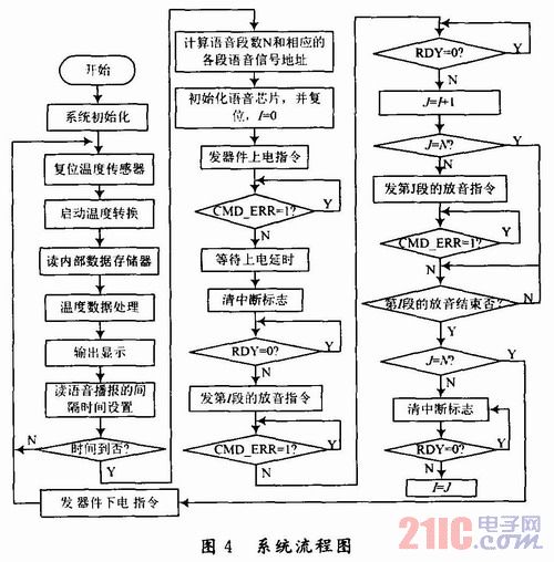
1.3 System Software Design The software flow of the system is shown in Figure 4.

After the system is initialized, the temperature sensor is reset, the temperature conversion is started, the temperature data is read, and the processing is performed. When the temperature is in a rapid change process, the system continuously collects and displays the temperature signal to determine whether the interval of the voice broadcast arrives. When the requirements are met, according to the measured current temperature value, the values ​​of the ten, one and decimal places are taken out, and then the corresponding voice signal entry address is obtained, the voice chip is reset, the power-on command is issued, and the time delay is issued. About 25 ms, to determine whether it has been powered on normally. After normal power-on, it is necessary to clear the interrupt flag to determine whether the device is ready to receive the next instruction. When ready, send the first-stage information playback command, and then check the status. The register determines whether the device normally executes the instruction just sent. After normal execution, it determines whether the device is ready to receive the next instruction. Only when the device is ready, can the next instruction be sent to the device. Otherwise, the instruction may be caused. Lost. The program considers the FIFO buffer inside the device, so that the N-segment voice signal is played like a voice, and there is almost no dead time interval between each voice. When the voice broadcast is completed, the voice chip loses power, completes a voice broadcast, and the program returns to the beginning of the system to prepare for the next temperature acquisition, processing, display, and voice output process.
2 Conclusion The digital voice thermometer designed by voice prompt and digital display has high precision and fast temperature measurement. It can be used for measuring body temperature as well as temperature of food, water and other materials. Convenient, not only for ordinary families but also for some industrial field production applications that require voice prompts.
BLPS laser safety protective device is designed for personal safety used on hydraulic bender.
The dynamic test technology it used has passed the Type 4 functional safety assessment by TUV, and get the national invention patent. The product reaches the advanced technological level of similar products.
BLPS laser safety device provides protection zone near the die tip of the bender to protect fingers and arms of the operator in close to the upper mold die tip. It is the most effective solution so far to preserves the safety and productivity of the bender.
Press Brake Protection,Laser Guarding Device,Press Brake Guarding Systems,Press Brake Guarding
Jining KeLi Photoelectronic Industrial Co.,Ltd , https://www.sdkelien.com