DP83640 synchronous Ethernet mode: achieve sub-nanosecond accuracy in PTP applications
1.0 Introduction
The unique performance of National Semiconductor's DP83640, Synchronous Ethernet technology at 100Mb / s, enables very precise synchronization between IEEE1588 Precision Time Protocol (PTP) systems connected by Ethernet. Using this feature, you can work within the required network topology constraints and achieve PTP applications to achieve sub-nanosecond master-slave synchronization accuracy. It can also generate a slave node clock output that is locked and calibrated to the master PTP clock.
This application note first provides a summary of the empirical results obtained by using synchronous Ethernet mode to measure the synchronization of master and slave nodes. Then, it provides background information about the working principles and topology limitations related to the synchronous Ethernet mode. Next, typical applications are discussed, and the potential accuracy of using synchronous Ethernet mode is clearly explained through empirical data. This application note applies to the following products: DP83640
2.0 Measurement synchronization
Synchronization accuracy can be defined as the instantaneous time difference between the master clock counter and the corresponding synchronized slave clock counter. The synchronization accuracy can be determined by measuring the time difference between the master signal triggered at a specific time and the corresponding slave signal triggered by the local synchronized clock counter at the same time. Generally, in the context of PTP discussions, these trigger signals occur every 1 second, so they are defined as the average pulse per second, or PPS (second pulse) signal.
According to the accuracy of master-slave synchronization, the phase relationship of the master-slave PTP clock output that controls the PTP counter can also be directly measured.
The measurement is repeated during the extended period, and the collected statistical data can provide the average value, standard deviation, and a maximum time or "peak-to-peak" difference between the master and slave clocks or PPS signals.
When the slave device is connected and synchronized with the master device, a fixed phase relationship is established between the master and slave PTP clocks. The average value of the statistical data accumulated in a specific time is used to measure this fixed phase relationship. The degree of this phase relationship change is limited by the accuracy of the internal PTP counter. In the DP838640T device, the internal PTP counter (or digital clock) is continuously updated in 8ns increments at a frequency of 125MHz. Therefore, the fixed phase relationship, or the average value determined between the master and slave devices varies from + 8ns to -8ns. Any asymmetry in the physical bidirectional path between the master PTP clock and the slave PTP clock will also cause additional changes.
As long as the synchronous connection is maintained, the average value will remain constant. However, when the connection is disconnected and re-established, a new, fixed average value within the limits of the sampling clock is determined.
For the purposes of this article, the term "accuracy" is used to describe the standard deviation measured between a master signal and a slave signal that meet a fixed average value when synchronization is established.
3.0 Summary of results
In a point-to-point PTP system configured for synchronous Ethernet operation, tests conducted during the extended period under normal conditions have shown that the synchronization of the master clock to the slave clock can achieve an accuracy of better than 100ps, and the measured peak-to-peak value is less than 1ns. These results are approximately 100 times more accurate than similar tests when synchronous Ethernet mode is disabled.
The empirical data also illustrates the performance of the network lock and calibration of the generated slave clock up to 125MHz and connecting it to the PTP master clock. Using an external precision clock device, such as NSCLMK3000 series devices, can achieve a higher frequency locked clock.
Also note that if the synchronous Ethernet mode is enabled, any instability of the local slave reference clock can be eliminated because the slave PTP clock is locked to the master clock.
4.0 background introduction
The IEEE1588 precision time protocol provides network connection and packet-based synchronization between the master and slave systems. When only a pure software process is used, the synchronization accuracy obtained by the system is generally on the order of milliseconds.
Using the hardware-led advantage provided by the DP83640 in PTP-enabled point-to-point connections makes it possible to achieve synchronization accuracy better than 10ns.
In addition, enabling synchronous Ethernet mode makes it possible to achieve sub-nanosecond accuracy in point-to-point connections.
In order to utilize the synchronous Ethernet mode, the network system must meet certain topological constraints. To help explain these limitations, some key parameters, device internal clock structure, and network topology requirements are described below.
4.1 Important terms
Main node: The main node is a network node with Precision Time Protocol (PTP) enabled, which contains or propagates a main PTP clock signal and main PTP counter data.
Slave node: The slave node is a network node with PTP enabled, which contains a slave PTP clock and counter. The slave node is usually connected to a master node through the network. PTP is used to synchronize a slave PTP clock and counter to a master PTP clock and counter.
PTP clock: A PTP clock is the source of the output clock signal locked with the PTP counter. In DP83640, the local PTP clock works at 250MHz, and the configuration clock is used to control the CLK_OUT signal. This PTPCLK_OUT signal can be programmed to the divisor frequency of the 250MHz PTP clock with a divisor range from 2 to 255 (corresponding frequency is 125MHz to 0.98MHz).
PTP counter: The PTP counter contains time information and is locked with the PTP clock. On the master node, the PTP counter is a data source when using the precision time protocol, and the purpose is to synchronize the counter in the PTP slave node. The increment value of the PTP counter is 8ns.
Local reference clock: The local reference clock is used to generate network traffic. The local reference clock is embedded into the transmitted network information stream and recovered from the network information stream at the receiver node. All Ethernet physical layer devices use a local reference clock source. The local reference clock operating frequency within DP83640 is 125MHz.
4.2 Key configuration requirements
When a network node performs the function of a PTP slave device, the node must be connected to a docking point (a node, switch, or repeater) to provide access to the master PTP clock. The PTP protocol must be enabled and active.
In addition, the docking point must lock its local reference clock to the PTP master clock. If PTP clock phase alignment is also required between the master and slave devices, the PTP master clock must be phase aligned with the master PTP counter. (For information on the phase alignment of the output clock in the DP83640, please refer to the application note AN-1729– "DP83640IEEE1588PTP Synchronous Clock Output".) It is also important to use it only as a device for the slave PTP clock Can synchronize Ethernet mode. Enabling synchronous Ethernet mode in the main node will produce undesirable results.
4.3 Enabling synchronous Ethernet mode
The synchronous Ethernet mode is only enabled on the node designated as the slave node. Just set the SYNC_ENET_EN bit of the PHYCR2 extended page 0 register to 1 (Reg0x1C: 13 = 1) to enable synchronous Ethernet mode.
4.4DP83640 clock structure
The DP83640 has several internal clocks, including a local reference clock, an Ethernet receive clock, and a PTP clock signal source. It also includes an internal PTP digital counter and logic that can control the digital counter and PTP clock rate (frequency) (see Figure 1).
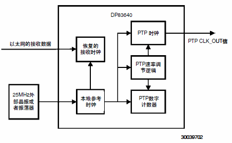
Figure 1. DP83640 internal clock with synchronous Ethernet mode disabled
An external crystal or oscillator provides excitation to the local reference clock. The local reference clock becomes the core of all clocks in the device. Restore the receive clock from the received Ethernet packet data stream and lock to the transmit clock in the docking point. In normal operation, the IEEE1588PTP package is used to match the PTP clock and counter in the slave device with the PTP clock and counter in the master device. This matching can be accomplished by controlling the rate adjustment logic.
When synchronous Ethernet mode is enabled, the control of the PTP clock, digital counter, and PTP rate adjustment logic is switched from the local reference clock to the recovered receive clock (see Figure 2). This has the effect of locking the PTP clock and counter of the slave system to the PTP clock and counter of the master system. Finally, synchronization accuracy will increase significantly (see Figure 3).
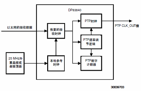
Figure 2. DP83640 internal clock with synchronous Ethernet mode enabled
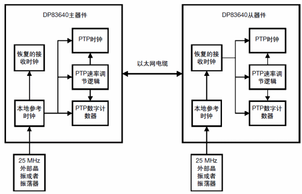
Figure 3. Working block diagram of DP83640 enabled in synchronous Ethernet mode in a point-to-point network topology
4.5 System topology considerations
As mentioned earlier, in order to work in synchronous Ethernet mode, the master node reference clock must be locked with the master PTP clock. This is the default configuration when the DP83640 local reference clock uses a PTP digital counter and PTP clock. If an external PTP clock source is used in the main system, an external PLL can be used to lock the reference clock source to the external PTP clock.
Note that there is no need to use a DP83640 device at the master PTP clock node in order for the attached DP83640 slave node to work in synchronous Ethernet mode. It is sufficient to phase lock an external PTP clock to the reference clock input of any Ethernet physical layer interface device (Phy).
If you use a multi-port hub or switch structure that can synchronize all Ethernet channels to the master PTP clock, you can synchronize multiple slave devices to a single master clock. See Figure 4.
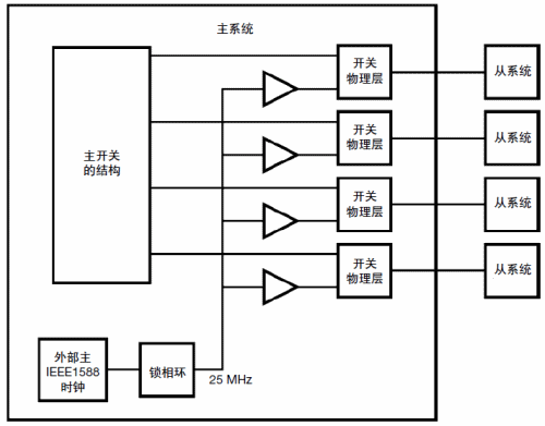
Figure 4. Switching topology of the distributed master clock
Similarly, synchronous Ethernet mode operation may be propagated through a switch tree structure, where each slave switch node synchronizes itself with the main network source. (See Figure 5)
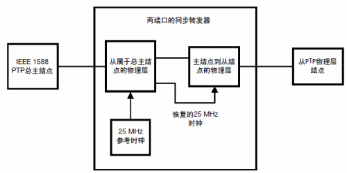
Figure 5. Two-port synchronous repeater system
5.0 Typical Application
A typical application of synchronous Ethernet mode is to require very accurate data recording instruments. Using the distributed nodes in Figure 4, a master system will trigger an excitation, such as an energy surge, and each slave node can represent an accurate instrument or sensor that can be used to measure the excitation effect at a precise time.
In addition, some applications will require a locked clock signal to be propagated on several instruments in the local network. If the peak-to-peak accuracy of 1 ns is given when the synchronous Ethernet mode is enabled, a 125 MHz output clock can be used to trigger several instruments and sampled data synchronously. Using the output clock of the device to control the external PLL clock source, such as National Semiconductor's LMK3000 series devices, can obtain a larger frequency selection range.
Finally, because the frequency of the master clock is transmitted through the network, when the synchronous Ethernet mode is enabled, the stability of the local oscillator is not an important source of error.
The stability of the slave node directly depends on the stability of its corresponding PTP connection master node. Therefore, no special environmental control is required to maintain synchronization accuracy. Using a high stability OCXO slave node will achieve the same level of accuracy as a standard 25MHz crystal.
6.0 Setting for simultaneous measurement
As mentioned before, using an oscilloscope to compare the time delay between the output signal of the master clock or node and the corresponding synchronization signal of the slave node, the accuracy of synchronization can be measured. Typically, the master-slave output signal is connected to the input terminal of the oscilloscope. Use the master signal to trigger the oscilloscope and rely on the master trigger signal to measure the slave signal time.
Some oscilloscopes have a histogram function. By accumulating a large number of samples of the output signal from the node, the relatively synchronized statistical information from the node to the master node can be determined. In the IEEE1588 application, the synchronization performance is generally measured by connecting a PPS trigger output of the master device to the corresponding PPS signal output from the slave device.
Using the DP83640 to measure synchronization, you can use an output trigger (including a periodic PPS output trigger), or use the actual PTP clock signal, which can be achieved by programming the output on the device's CLK_OUT pin (pin 24). See Figure 6.
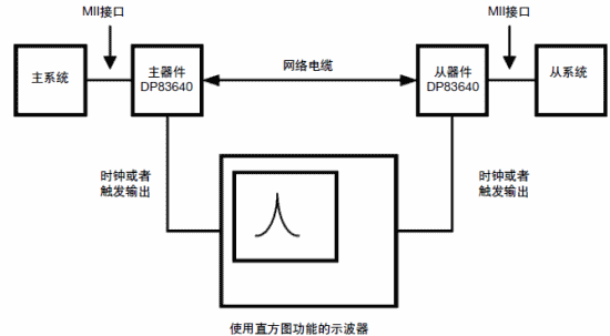
Figure 6. Settings for simultaneous measurement
According to the purpose of this application note, two DP83640 demo boards are used as master and slave devices for measurement, and a 1 meter cable is used for connection. The main device adopts OCXO25MHz reference clock source. The slave device uses OCXO and crystal oscillator to show that the synchronous Ethernet mode provides anti-interference performance against local temperature / frequency instability. The measurement is performed under normal conditions such as room temperature of 25 ° C and VCC of 3.3V. Using Tektronix784C oscilloscope.
7.0 measurement results
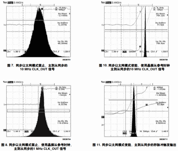
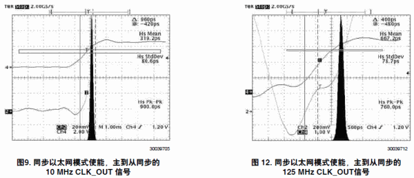
Table 1 summarizes the long-term (several hours) accumulation of synchronized data under normal conditions. The statistical data represents the time that the trigger signal of the master oscilloscope and the corresponding slave signal are measured in the extended period. The related histogram of each row in the data table is also shown with an additional oscilloscope.
For comparison, the test number 1 in Table 1 (Figure 7) represents the synchronous data collected when synchronous Ethernet mode is disabled. The master and slave devices use a very stable OCXO reference clock source to measure data. It can be seen that when the master clock is used as the reference, the standard deviation of the measured slave clock distribution is about 5ns, and the maximum peak-to-peak value is about 48ns.
Test number 2 (Figure 8) shows the data collected in the same configuration when the synchronous Ethernet mode is disabled, but the crystal is compared as a slave reference clock source. It can be found that when the maximum peak-to-peak value measured is about 119 ns, the standard deviation almost doubles to about 9.5 ns. If the maximum peak-to-peak result is greater than 100ns, it is impossible to obtain a stable 10MHz signal histogram trace, so a 1MHz clock output signal will be used instead.
For comparison, test number 3 (Figure 9) shows that the standard deviation is about 80ps when synchronous Ethernet mode is enabled, and the peak-to-peak measurement is about 900ps at this time. The measured accuracy is more than 50 times higher than the corresponding data when the synchronous Ethernet mode is disabled (Test No. 1, Figure 7).
Test number 4 (Figure 10) shows the data tested in the same configuration when the synchronous Ethernet mode is enabled, but the crystal is used again as the slave reference clock source for comparison. With a standard deviation of about 77 ps and a peak-to-peak value of about 700 ps, ​​the anti-jamming capability of the local clock instability provided by the synchronous Ethernet mode is clearly explained. Compared with the reference data in the Ethernet mode prohibition, the accuracy is about 100 times higher.
Test number 5 (Figure 11) can compare the data representing the 10MHzCLK_OUT signal with the data representing the synchronization of the second pulse trigger output. The data shows that when the standard deviation is comparable to similar 10 MHz CLK_OUT data (test number 3), the peak-to-peak value of the measured data is doubled to approximately 2 ns.
Finally, test number 6 (Figure 12) shows that when the standard deviation is about 79ps and the maximum amplitude is about 760ps, the performance from the 125MHz master clock to the slave clock output is comparable to the performance at 10MHz.
Table 1. Synchronous output test results

8.0 Conclusion
Through the empirical data provided, it can clearly explain the advantages of the synchronous Ethernet mode feature of National Semiconductor DP83640. It can be seen that the accuracy of the synchronous Ethernet mode enable can be improved by more than 100 times compared to the results obtained in a similar configuration when the synchronous Ethernet mode is disabled.
For any application that requires recording data to achieve sub-nanosecond accuracy, in a PTP-enabled network environment, the synchronous Ethernet mode is useful. Synchronous Ethernet mode is also useful for applications where the master clock source on the network link requires precise locking and expansion, or in applications where the synchronization slave system must be isolated from the instability of the local reference clock.
When the accuracy is significantly improved, in order to correctly apply the synchronous Ethernet mode, the required network topology must be met. These restrictions include locking the phase of the master PTP clock to the master physical layer clock, and directly connecting the phase-locked master PTP clock node and slave PTP clock node on the frequency-locked network link.
Lead Balls Granulating Machine
Granulating Machine,Plastic Granulator,Plastic Granulator Machine,Lead Balls Granulating Machine
Zhijiang BSL battery technology service company , https://www.bslbatteryservice.com