Every signal integrity engineer knows that analyzing closed-eye diagrams has never been easier. The frequency response (or lack of bandwidth) of the transmission channel can cause Inter-Symbol Interference (ISI), which is the culprit that causes the eyes closed. Before I wrote an article on closed eye analysis techniques, this time we will explore how to measure the ISI left behind after equilibrium, the so-called resident ISI. In this process, we will realize that the DFE is actually very simple.
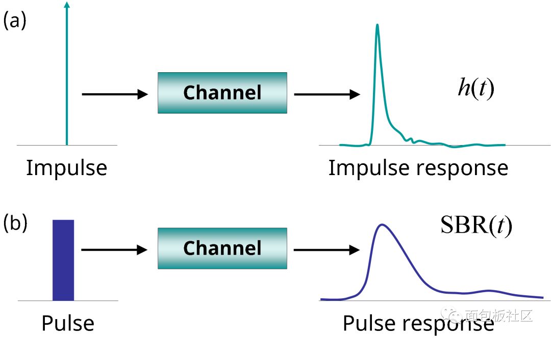
Impulse response is becoming more and more popular in defining the technical standards for high-speed serial buses. You can generate a pulse by sending a long string of zeros, followed by one, then another long string, by the pattern generator. That is, the pulse is a non-return-to-zero (NRZ) bit and the impulse response is the same as the SBR (single-bit response).
As with the impulse response, the impulse response also includes information about the circuit and the impedance of the track, connectors, cables, pins, and solder balls. Both amplitude and phase are built-in. You can even generate a crosstalk impulse response by transmitting a pulse on an aggressor and measure SBRx(t) on the receptor.
Figure 1 shows that (a) the narrow peak and (b) the impulse response are equivalent.

Figure 1: The limited bandwidth of the transmission channel is extended by (a) a narrow peak, h(t); (b) a single bit, SBR(t). (Source: Anritsu Corporation).
The impulse response SBR(t) has a relationship with the narrow peak response h(t) as follows:

Where pulse(t) is a long string of 0s, a 1 (for PAM4, a 3), and another long string of 0s.
The impulse response SBR(t) can be measured in the frequency domain of a vector network analyzer (VNA) and either with time domain reflectometry/time domain transmissivity (TDR/TDT) or with an oscilloscope. Extracting from simulation is also easy.
Because the impulse response measurement provides all the information about the channel—all linear and time-invariant information about the channel—this should be everything we need to consider. Measurements and calculations for a particular performance variable include the channel operating margin ( COM) and Signal to Noise Ratio Distortion (SNDR).
In an actual system, the receiver discretely samples each symbol at a baud rate (ie, NRZ bit rate and half of the PAM4 bit rate).

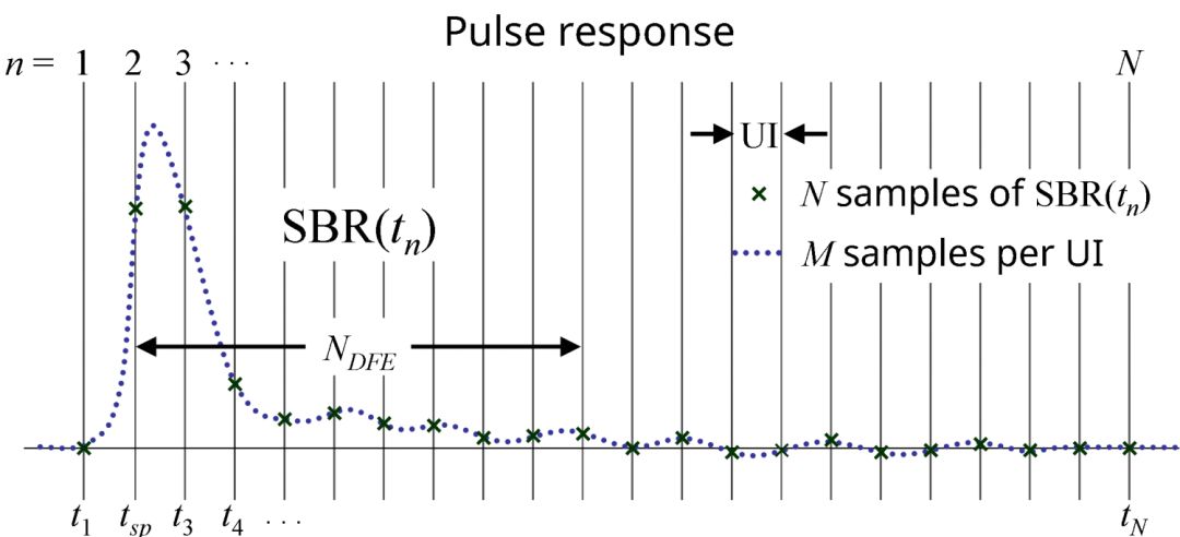
The sum is accumulated over the duration of the impulse response. The granularity and h(t) of SBR(t) are usually M=32 samples per unit interval (UI), as shown in FIG. 2 .

Figure 2: SBR(t) M samples per UI, producing a more detailed waveform than each UI sample. (Source: Anritsu)
The sampling point tsp is a UI after the initial rise of SBR(t).
Resident ISI, which can be called ResISI(n), is the ISI retained by each UI after equalization. To calculate ResISI(n), we need to include transmitter equalization in transmit bursts - de-emphasis or transmitter feedforward equalization (FFE). We also need to include the effect of the Receiver Continuous Time Linear Equalization (CTLE), which is easily implemented in IBIS simulators such as ADS (Keysight Advanced Design System). Decision feedback equalization (DFE) can be entered manually:

ResISI(n) is the difference between the pre-equalized impulse response and the post-equalized impulse response. Perfect equalization means that for all n, ResISI(n) = 0. The coolest part (I think it's cool) is how to explicitly include DFE with its tap b(n). This is obvious, right? But still incredible.
To get a single parameter measurement of the resident ISI, just add its component, root sum of squares, just like adding a side to a right triangle.
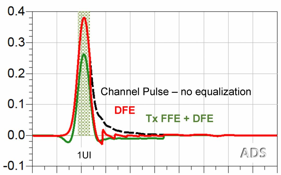
You can see in Figure 3 how the three equalizers affect the pulse.

Figure 3: ADS IBIS simulation with and without an equalized impulse response.
The same method can be used to use SBRx(t) to calculate how the equalization scheme affects crosstalk. With the intrusion SBR and SBRx, the post-equalization shape of any waveform can be calculated by explicitly including the DFE (as we did with ResISI). That is, you can see what the waveform looks like on a slicer that is deeply implanted inside the receiver.
ZGAR Aurora 3000 Puffs
ZGAR electronic cigarette uses high-tech R&D, food grade disposable pod device and high-quality raw material. All package designs are Original IP. Our designer team is from Hong Kong. We have very high requirements for product quality, flavors taste and packaging design. The E-liquid is imported, materials are food grade, and assembly plant is medical-grade dust-free workshops.
Our products include disposable e-cigarettes, rechargeable e-cigarettes, rechargreable disposable vape pen, and various of flavors of cigarette cartridges. From 600puffs to 5000puffs, ZGAR bar Disposable offer high-tech R&D, E-cigarette improves battery capacity, We offer various of flavors and support customization. And printing designs can be customized. We have our own professional team and competitive quotations for any OEM or ODM works.
We supply OEM rechargeable disposable vape pen,OEM disposable electronic cigarette,ODM disposable vape pen,ODM disposable electronic cigarette,OEM/ODM vape pen e-cigarette,OEM/ODM atomizer device.

Aurora 3000 Puffs,ZGAR Aurora 3000 Puffs Pod System Vape,ZGAR Aurora 3000 Puffs Pos Systems Touch Screen,ZGAR Aurora 3000 Puffs Disposable Vape Pod System,3000Puffs Pod Vape System
ZGAR INTERNATIONAL(HK)CO., LIMITED , https://www.zgarette.com