Foreword: This paper aims to introduce a simple dielectric waveguide dual-mode filter design method to guide the filter engineer to design the base station dielectric waveguide filter.
One: IntroductionWith the development of small, lightweight, and high-performance communication system equipment, higher requirements are also placed on front-end frequency selective devices. With the gradual determination of 5G communication system standards, the best choice for high performance, small size, lightweight dielectric waveguide filters.
This paper introduces a design method of dielectric waveguide dual-mode filter, which is used by less experienced filter design engineers to learn.
Two: Introduction to dielectric waveguide filtersThe dielectric waveguide filter explained in this paper has a high Q value, low loss, and large power capacity based on the TE mode dielectric waveguide dual mode filter. Therefore, when designing such a dual-mode filter, whether the previous multi-port computing design method can be used is the focus of this paper.
The following figure shows the four modes in a single resonator:
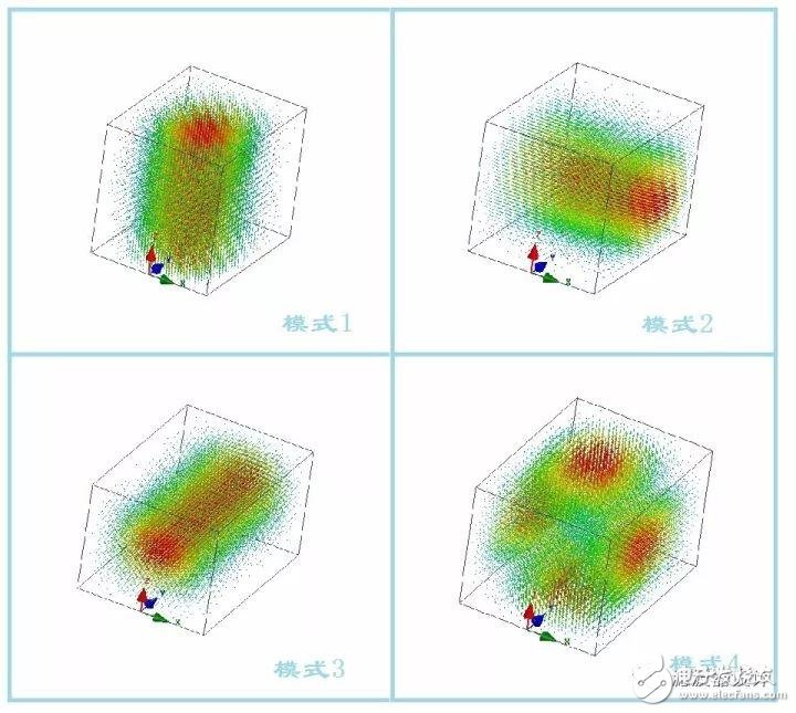
It can be observed from the above electric field distribution diagram that the single cavity dual mode and the single cavity three mode can be freely selected. At the frequency point where the high-order mode appears, the high-order mode is optimized by selecting the dielectric constant and controlling the size of the cavity. Try to pull out the frequency of high-order modes and reduce the impact on the passband.
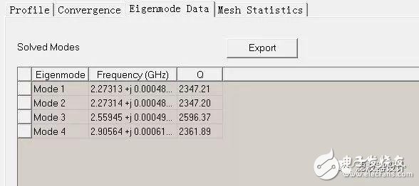
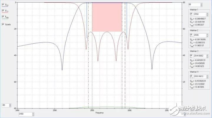
Three: the design process3.1 The design of the multimode filter, the evaluation of the pass-through performance is the same as the evaluation of the single-mode, except that in the evaluation of the Q value, the Q value of the multi-mode is higher than that of the single-mode, which can be based on the eigenmode. Observed in the simulation. The following figure shows the simulation results of a two-cavity 4-mode filter:
3.2 Coupling bandwidth and input and output QL
Calculating input and output coupling in 3.3HFSS
The input-output coupling is calculated in HFSS, and the magnitude of the alignment delay can be used to initially determine the input-output coupling strength. In the simulation, the insertion direction of the connector probe needs to follow the direction of the electric field of a certain mode. As shown below:
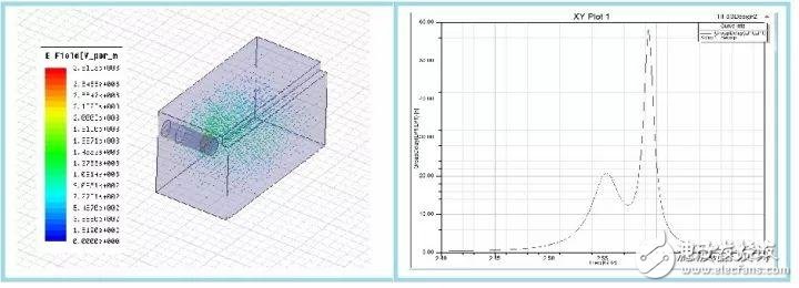
When determining the input-output coupling, other modes need to be separated due to the influence of the second mode or the third mode. Here, due to the coupling between the 1, 2 modes, the delay waveform is bimodal. The method of frequency separation can be adopted to reduce the influence of the second mode on the first mode.
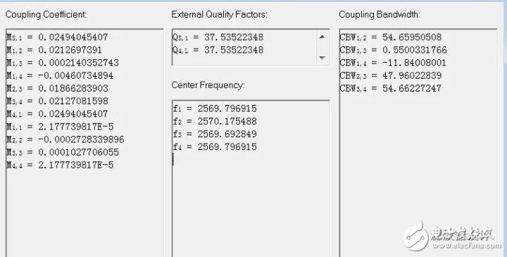
3.4 Calculation of coupling bandwidth and frequency
Here, the multi-port extraction method is selected, and the resonant frequency is extracted in the HFSS, and the coupled bandwidth is stored.
When simulating here, you need to pay special attention to the port's resume mode, which needs to follow the direction of the electric field. When calculating the coupling bandwidth, the frequency point at which the filter passband harmonic appears can be observed at the same time. By reasonably selecting the size of the coupling window and the opening direction, the harmonic amplitude of the high-order mode is minimized.
3.5 Filter passband calculation and optimization

For the optimization calculation of high-order multi-mode filters, the two-port S-parameter extraction method is usually used, and spatial mapping, genetic algorithms, etc. are also useful. Therefore, a reasonable choice of optimization methods can speed up the design, save time, and shorten the filter development cycle.
Summary: The above briefly introduces the design process of a multimode dielectric waveguide filter. It has the advantages of small size, light weight and excellent performance in the 5G communication system. It is believed that the application in 5G communication will be more extensive.
Dongguan Guancheng Precision Plastic Manufacturing Co., Ltd. , https://www.dpowergo.com