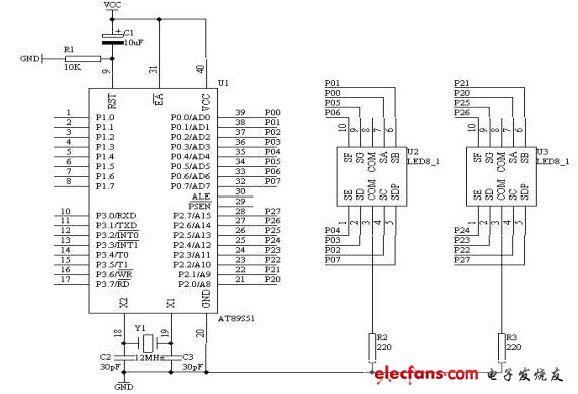
As shown in the figure below, the P0 and P2 ports of the AT89S51 MCU are connected with two common digital P0 ports to drive the display of the tenth time of the second time, while the P2 port drive displays the ones of the second time.
1. Connect the P0.0/AD0 - P0.7/AD7 ports in the "Microcontroller System" area to any of the a - h ports in the "Quad Static Digital Display Module" area with an 8-pin cable; P0.0/A D0 corresponds to a, P0.1/AD1 corresponds to b, ..., and P0.7/AD7 corresponds to h.
2. Connect the P2.0/A8 - P2.7/A15 port in the "Microcontroller System" area to the 8-a static digital display module area on any of the a - h ports; P2.0/A8 corresponds to a, P2.1/A9 corresponds to b, ..., and P2.7/A15 corresponds to h.

Aluminum Heat Dissipation Shell
Aluminum Heat Dissipation Shell,Heat Dissipation Shell,Aluminum Heatsink,Heat Sink Extrusion
Original Electronics Technology (Suzhou) Co., Ltd. , https://www.original-te.com