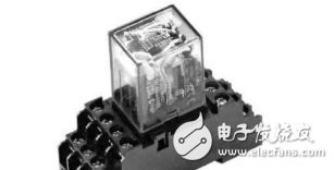
Several types of devices are carefully designed with a series-parallel structure. Relays are not allowed to be connected in parallel to provide larger currents, two capacitors, or two switch-type tubes (IGBTs, transistors, MOSFETs, etc.) that are not used in a series configuration to solve the problem of a single under-voltage.
The reason is: when the switch is expected to be turned on synchronously, the actual synchronization of the two can not be achieved. The potential difference caused by such a small difference is that one is conducting and the other is not yet conducting. When all the withstand voltage is applied to one tube, it is easy to cause damage to the device. This is actually a series model that is easy to cause problems in the reliability model. It is not the two that we understand from the functional design. The parallel model implemented by the pressure.
The two relays provide a large current in parallel, and the synchronization of the contacts of the relay is also difficult to ensure. Thus, at the initial stage of the startup, the conduction is always just turned on, and the other is not yet turned on, which easily causes the relay contacts to stick.
The series connection of capacitors is because the capacitance error of capacitors is large. When used in series, the voltage division on them will be relatively large. Therefore, it is better to have a resistor on both ends of each capacitor (the ratio of the two resistance values) The ratio of the capacitance of the capacitor to the capacitor is the same, and the resistance is not too small, so that the static current is high and the static power consumption is high. 
SHENZHEN CHONDEKUAI TECHNOLOGY CO.LTD , https://www.szfourinone.com