Vibrating wire sensors are one of the more advanced sensors in stress and strain measurement. The output of the vibrating wire sensor is a frequency signal, and A/D and D/A conversion are not required in the signal processing process. Therefore, the anti-interference ability is strong, the signal transmission distance is long, and the transmission cable is required to be low. In addition, the vibrating wire type sensor has the characteristics of simple structure, high precision and long service life, and thus has been concerned by the engineering community. In engineering applications, vibrating wire sensors can be embedded or welded to the tested parts, and there is basically no problem of aging and shedding of the adhesive, which has good stability and repeatability. For small changes in the measured force, a large frequency change can be produced with high sensitivity.
With the development of modern electronic reader technology, materials and production processes, vibrating wire instrument technology has also been continuously improved, becoming the trend of a new generation of engineering instruments, widely used in building foundations, dams, bridges, highways, nuclear power plants. Cement shells and the like need to be used for measuring force, displacement, and micro cracks, and can also be used as key sensors for electronic scales, belt scales, and automobile scales. In order to accurately measure the changes in stress and strain, in addition to studying the material properties of the vibrating wire sensor, it is necessary to solve the vibration and frequency reading technology of the vibrating wire sensor. To this end, this paper studies the excitation technology and frequency measurement technology of the vibrating wire sensor, and introduces the frequency sweep excitation technology of the multi-channel vibrating wire sensor based on the comparison output mode in the PIC16F873 microcontroller.
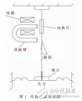
1 Traditional intermittent excitation methodIn order to measure the natural frequency of the vibrating wire, it is necessary to try to excite the string vibration. There are generally two ways to stimulate string vibration: (1) continuous excitation mode. This method is further divided into a current method and an electromagnetic method. In the current method, the vibrating wire is used as a part of the oscillator, and the current is passed through the vibrating wire, so the insulation problem between the vibrating wire and the outer casing must be considered. If the difference between the thermal expansion coefficient of the insulating material and the vibrating wire is large, the temperature difference is likely to occur, which affects the measurement accuracy, and the continuous excitation easily makes the vibrating wire fatigue. (2) Intermittent excitation mode. As shown in Figure 1, the vibrating wire is equipped with a small piece of pure iron, and an electromagnet is placed next to it. When the electromagnet coil is connected to the pulsating current i, the magnetism of the electromagnet is greatly enhanced, thereby attracting a small piece of iron (vibrating wire); When no current flows through the coil, the electromagnet releases the vibrating wire. When the cycle is excited, the strings vibrate. To maintain continuous vibration of the string, the vibrating wire should be constantly excited. That is, the electromagnet passes a pulse current at regular intervals to cause the electromagnet to periodically attract the vibrating wire, so that a pulse current of a certain period must be passed through the coil of the electromagnet. When the excitation is stopped, the vibrating wire continues to do the damping vibration due to the action of inertia, and the induced electromotive force is generated in the electromagnet coil, and the frequency of the induced electromotive force is equal to the damping vibration frequency of the string. This allows the natural vibration frequency of the vibrating wire to be measured from the frequency of the output potential.

This intermittent excitation circuit is complicated and usually consists of a relaxation oscillator, an electromagnetic relay, and a power supply. The electromagnetic relay has large volume, large power consumption, poor reliability of mechanical contact operation, and the oscillation frequency adjustment range of the oscillator is not large, and the adjustment cannot be realized automatically on the line, so that it is sometimes difficult to start the vibrating string [2]. When multiple multi-channel vibrating wire sensors are to be monitored simultaneously, the circuit becomes more complicated. More serious is that the excitation coil driven by the relay is an inductive load, which generates large electromagnetic interference during intermittent excitation, which affects the monitoring accuracy and causes interference to the normal operation of other circuits. In order to solve these problems, a time division multiplexing method is adopted for the frequency sweep excitation of the multi-channel vibrating wire sensor. That is, the multi-channel sensor shares a sweeping signal source. When a certain sensor is to be inspected, the sweeping signal source is connected to the sensor by the selection switch; the electromagnetic relay is replaced by a MOS FET relay. In this way, not only the circuit is simplified, but also the electromagnetic interference problem is well solved.
35Kv Steel Pole,Stainless Steel Poles,Metal Sign Posts,Galvanised Metal Posts
Jiangsu Baojuhe Science and Technology Co.,Ltd. , https://www.galvanizedsteelpole.com