Regarding the setting and resetting of the MCU, it is to initialize the circuit to a certain state. Generally speaking, the function of the MCU reset circuit is to initialize a state machine to an empty state, for example, in the MCU, when the MCU is reset, the MCU is Some registers and storage devices are loaded with a value preset by the manufacturer.
The principle of the reset circuit of the MCU is to connect the resistor and capacitor on the reset pin rst of the MCU to realize the power-on reset, and the reset time is (clock cycle = 12 × oscillation period, oscillation period = 1 / f), this time can only be large Small, the specific value can be calculated by the rc circuit time constant.
The status of each register after reset of the microcontroller
A=00H, indicating that the accumulator has been cleared; PSW=00H, indicating that register 0 is the working register group; SP=07H, indicating that the stack pointer points to the on-chip RAM 07H byte unit, according to the stack operation first and then press The first content that is pushed in is written into the 08H unit; Po-P3=FFH, indicating that 1 has been written to each port line. At this time, each port can be used for both input and output; IP=× × × 00000B, indicating that each interrupt source is at a low priority; IE = 0 × × 00000B, indicating that each interrupt is turned off;
Setting can initialize it to any state. Reset and set means to set the logic value of the device to a specific value. Generally, I understand that "reset" generally means setting the Q output of the register to 0. Bit" means that the output of the Q terminal of the register is set to 1. This operation can be implemented by using the setb instruction of the microcontroller. 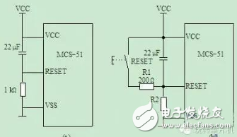
We make OBD connector with terminal by ourselves, soldering type and crimping type are both available. Also 12V and 24V type. OBD1, OB2, J1939, J1708, J1962, etc. Also molded by different type, straight type or right-angle type. The OBD connector cables used for Audi, Honda, Toyota, BWM, etc. We have wide range of materials source , also we can support customers to make a customized one to replace the original ones.
Sae J1708 Connector,Sae J1939 Connector,OBD2 Diagnostic Connectors,Diagnostic Connector,Deutsch Diagnostic Connector
ETOP WIREHARNESS LIMITED , https://www.wireharnessetop.com