Abstract: This application note describes how to use Maxim's TDM-over-Packet (TDMoP) chip to provide network loopback support for FDL (data connection equipment). This article focuses on the TDMoP product line. DS34T10x represents a variety of devices, specifically: DS34T108, DS34T104, DS34T102, DS34T101.
introduction
In many applications, system administrators need to operate support systems (OSS) to control and manage network devices. Using OSS, administrators can issue commands to "test probes" to enable or disable FDL network loopback. This application note describes how to implement these FDL commands using the DS34T10x series of TDMoP devices.
FDL loopback command function
In typical applications, FDL loopback commands are generated in the test section (Figure 1).

Figure 1. FDL enables or disables the loopback test in the test section
As a part of system maintenance, the test probe is used for FD L loopback whenever a TDM line fault report is received. It can be used as a diagnostic tool to locate the fault location. In the traditional T1 network, the TDM line is connected to the test probe, and a loopback command can be sent to evaluate the result.
When the network is operating normally, TDM traffic terminates at the customer premises equipment (CPE). Consider the network shown in Figure 1. When a network failure is detected, the network will be placed in maintenance mode; commands issued from the OSS pass through the TDM gateway and then pass through the ONU or ONT. In this example, the TDM gateway supports circuit emulation services (CES), which means that the TDM gateway is the end point of the CES pseudowire. All CES channels terminate at the TDM gateway. The ONT or ONU can also be GPON. Therefore, GPON transmission ends here. In this case, the TDM gateway requires the ONU to terminate the transmission of GPON services and CES services. In Figure 1, ONU is implemented using Maxim's TDMoP chip. You can see a connector (SJ) in the picture, which is usually used in many traditional PDH networks.
Internal hardware connection
In order to implement the network loopback defined by the GR-312-CORE standard, two FDL commands are required.
Turn on the network loopback ((00010010 11111111)). This bit command and response information is transmitted in the ESF data link, which will put the SJ in the maintenance state and loop back the received T1 data. When sending the loopback start message, SJ has been maintained in the maintenance state. The TDMoP device will monitor the 9th to 14th (001001) data to execute the loopback command.
Close the network loopback (00100100 11111111). This bit of command and response information is transmitted on the ESF data link, which will put the connector into a normal working state, which is equivalent to a T1 relay. The connector prohibits the command to keep the device in a normal state during the transmission loopback. TDMoP will monitor the 9th to 14th bits (001001) to execute the loopback prohibition command.
The opening and closing commands of these loops can be realized by the DS34T10x chip. Figure 2 shows the hardware connection of the DS34T10x LIU and the framer.
To enable loopback on and off, each T1 port requires an additional T1 framer. As shown in Figure 2, if two T1 port loopbacks are implemented in the network, two additional T1 framers are required to form a frame loopback (FLB). In this example, a piece of DS34T104 is used with 4 T1 ports (two for the required T1 ports and two for FDL loopback). If you need 8 T1 ports, you can use DS26401 to provide another 8 framers. These additional framers are used to connect to the original framers; these framers are only used for loopback on and off operations. In Figure 2, a piece of DS34T104 is used to realize the TDMoP "binding" of two T1 ports, and provides loopback support.
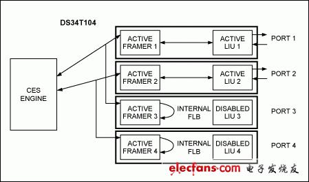
Figure 2. Example of DS34T104 supporting loopback on and off
In FIG. 2, the framer 3 is connected to the framer 1 in parallel, and the framer 4 is connected to the framer 2 in parallel. It needs to be pre-configured before sending FDL opening and closing codes. You can contact Maxim to apply for drivers and configuration files. To verify this configuration, configure the FMRTOPISM4 register as follows:
Set FMRTOPISM4.FRMR3 = 000, so FRMR3 is derived from FRM1
Set FMRTOPISM4.FRMR4 = 001, so FRMR4 is derived from FRM2
Since FDL can only work in T1 ESF framing mode, ports 3 and 4 should be configured as follows:
Set TCR3.TFM = 0
Set RCR1.RFM = 0
Next, configure the chip to transparent transmission mode through the control register 1.
TCR1 = 64h or 60h, depending on whether a B8ZS code is required
Then, through the reception control register 3, the framer 3 and the framer 4 are configured as frame loopback.
RCR3.FLB = 1 Framer 3 and 4
For the BOC received by port 3 and port 4, it can be set to a series of monitoring codes N (N = 1, 3, 5 or 7) through the RBOC register:
RBOC [2: 1] = 00: the first group of continuous BOC codes to identify valid sequences
RBOC [2: 1] = 01: The third group of continuous BOC codes to identify valid sequences
RBOC [2: 1] = 10: Group 5 continuous BOC codes, to identify valid sequences
RBOC [2: 1] = 11: Group 7 continuous BOC codes, to identify valid sequences
A valid BOC event is detected (as shown above, by setting RLS7.BD), the RBOC message needs to be read from the RBOC register. Then based on the RBOC message, the loopback can be set through the LMCR register.
LMCR [2: 0] = 010
The driver provided by Maxim contains such a command code in the _te1DrvCTRL function, which can be used to send any BOC data.
TE1DCTRL_T1403TXPKT
TE1DCTRL_T1403TXBOC
All drivers (including internal and external) can be called through a simple API of agent.c and t1e1_interface.c file.
A BOC code sending request can be in the following format:
// Call the driver's transmit BOC funcTIon
retval & = (* lnPtr-》 drvCtrl) (DRVREF, TE1DCTRL_T1403TXBOC, ENABLE, (INT) BOC_CODE);
A BOC code stop sending request can be in the following format:
// Call the driver's transmit BOC funcTIon
retval & = (* lnPtr-》 drvCtrl) (DRVREF, TE1DCTRL_T1403TXBOC, DISABLE, NULL);
in conclusion
ONU equipment is required to support FDL network loopback startup / shutdown commands. The TDMoP chip of the DS34T10x series supports analog loopback and can achieve this function. When the BOC receives a valid loopback command, it can enable analog loopback; similarly, it can also cancel loopback. This function of DS34T10x is an ONU designed with DS34T10x and does not require internal switches.
iDealTek-Electronics has accumulated rich application experience and design technical knowledge in the field of High-voltage power supplies, from Linear High Voltage Power Supplies based on power frequency transformers to Switching High Voltage power supplies based on IGBT components, from 60KV, 1KW High Voltage Power Module, to 5KV ~ 40KV, 1KW 2U Laboratory High-voltage power supplies, and to 5KV ~ 60KV, 2KW 4U and 5KV ~ 100KV, 6U rack-mounted capacitor charging high-voltage power supplies, and then to floor-standing cabinet-type high-current high-power high-voltage power supplies, all our high voltage power supplies are featured for high reliability, excellent high-voltage output stability and low-ripple electronic characteristics.
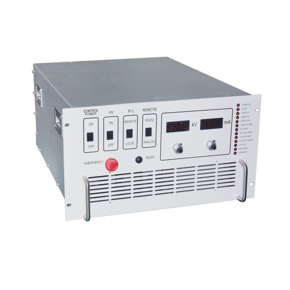
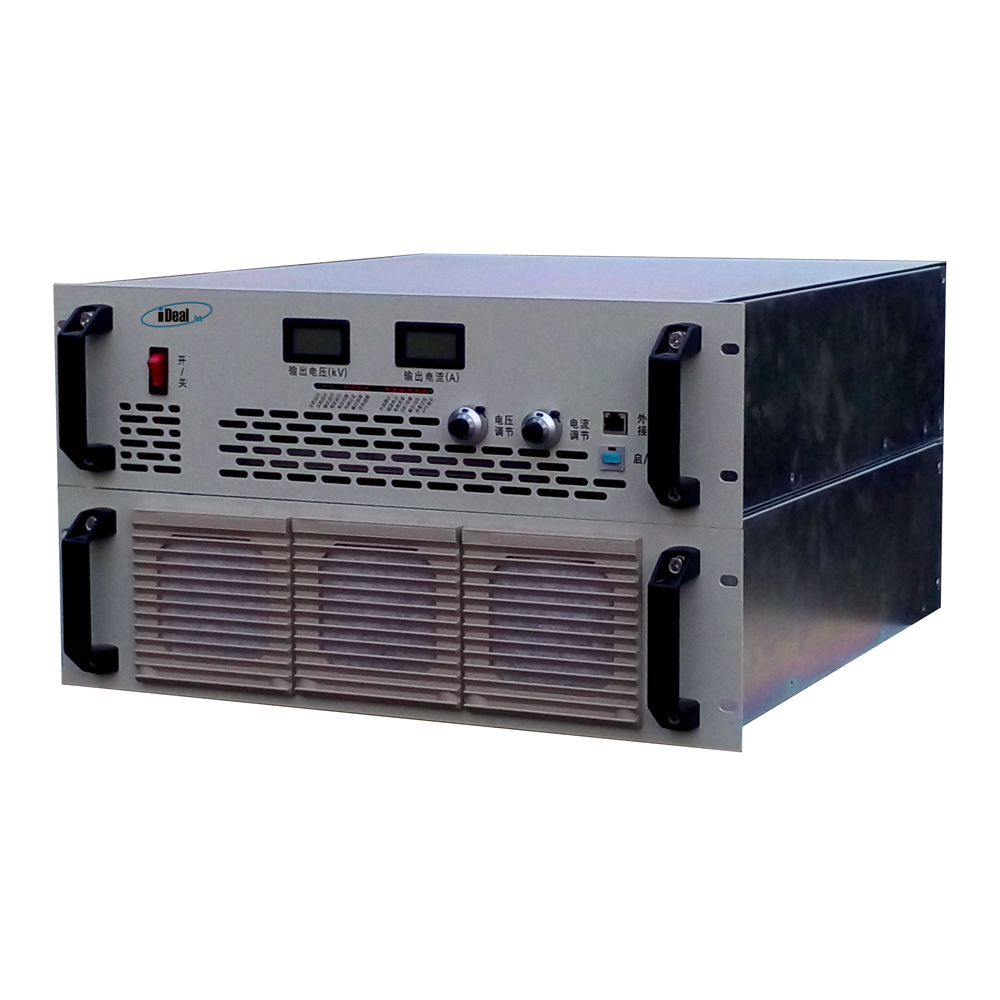
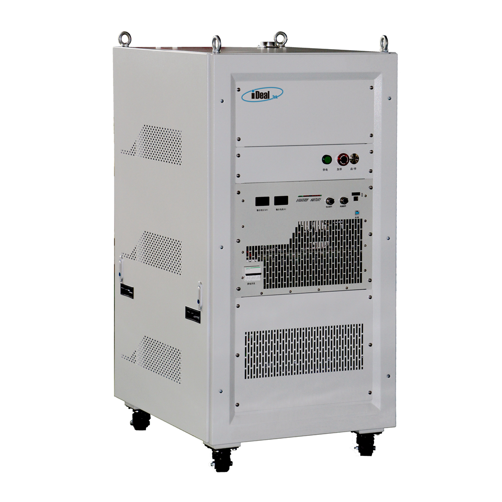
Through the reliable and durable operation panel on the front panel of the high-voltage power supply, the output voltage and current can be easily set and controlled. The high-precision LED or LCD ensures intuitive and high-precision high-voltage output measurement functions. Our high-voltage power supplies can be equipped with a wealth of remote-control interfaces, such as RS232 / RS485 /DB15 / DB25 / DB50 analog signal interface, etc. for remote high-voltage enable and inhibit, high-voltage output control programming and data monitoring.
Our HV power supplies have complete built-in protection functions, such as overvoltage protection, ARC protection, load discharge protection, over heat protection, etc. The protection mechanism can start in transient time to ensure the safety and reliability of the power supply itself and customer loads under high-voltage output.
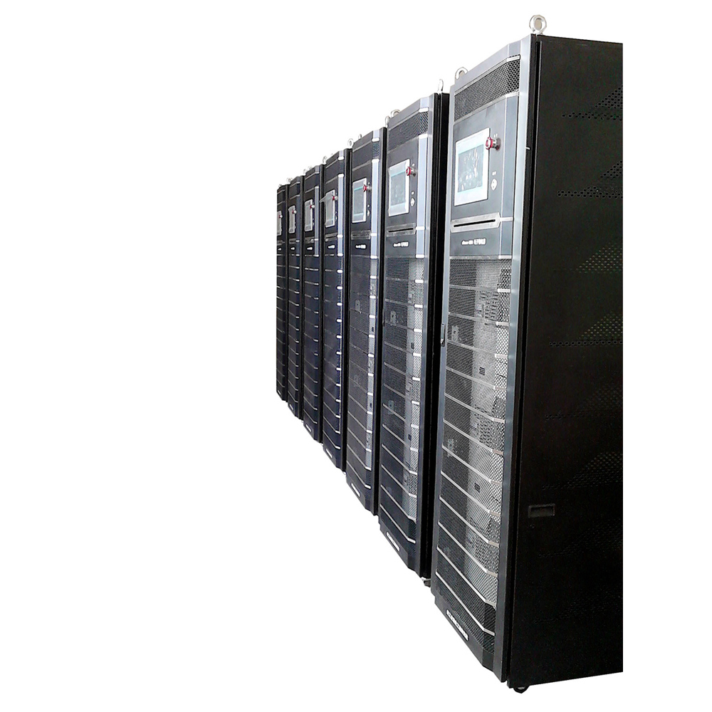
At present, our high voltage power supplies are widely used in high-voltage laboratories, capacitor charging, electron beam, ion implantation, FUSION power generation and other industries.
HV Power Supplies, High-voltage Power Supplies, High Voltage DC Power Supplies, HV PSU, High Voltage Power Module
Yangzhou IdealTek Electronics Co., Ltd. , https://www.idealtekpower.com