Hybrid stepping refers to the advantages of mixing permanent magnet and reactive, divided into two phases and five phases. The two-phase step angle is generally 1.8 degrees and the five-phase step angle is generally 0.72 degrees. The application is the most extensive.
In "HB type hybrid stepping motor structure and working principle detailed" we have already learned its structure and working principle in detail, then Xiaobian will lead everyone to learn more about HB hybrid stepping motor and phase number The relationship between the number of rotor teeth and the number of main poles. This paper first introduces the expressions of the phase number of the stepper motor, the number of teeth of the rotor and the number of main poles. Secondly, the general form of the phase and phase magnetic circuit is introduced.
Expression of phase motor phase number, rotor tooth number and main pole numberFor example, the HB type stepping motor is P phase, and the number of rotor teeth is based on the equation θs=180°/PNr. The step angle is θs=180°/PNr. At this time, the number of main poles of the stator 1 phase (the total of the "bar A" phase) is m, and is evenly arranged, and the number of teeth of the plurality of fine teeth arranged in the inner diameter is the same. The magnetic circuit for generating magnetic flux by the permanent magnet of the rotor forms a closed magnetic circuit between A "bar A" as indicated by a broken line in the figure below. It is not exactly the same as the odd-phase phases such as the three-phase HB and the five-phase HB type described later. A closed magnetic circuit cannot be formed between A "bar A", and it is necessary to form a closed magnetic circuit by connecting the other phases of B phase and C equal. The former is called the phase magnetic circuit type, and the latter is called the phase magnetic circuit type.
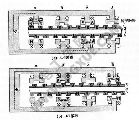
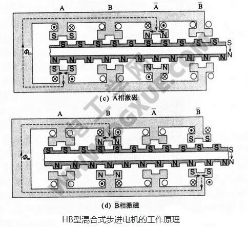
The two-phase HB type stepping motor is an in-phase magnetic circuit, and the three-phase HB type stepping motor has two forms of an in-phase magnetic circuit and an interphase magnetic circuit. The following figure shows a three-phase HB type stepping motor with 6 magnetic poles, no small teeth on the pole, and few rotor teeth. This figure describes the magnetic flux path of the stator and rotor, where (a) is the phase magnetic circuit. (b) is a phase-to-phase magnetic circuit.
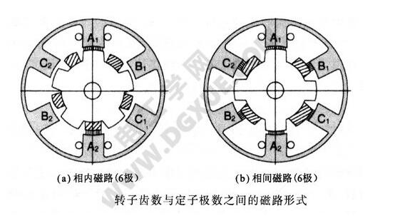
For example, in the case of the (a) phase internal magnetic circuit, when the stator main pole A1 and the adjacent B phase B1 or the C phase C2 are excited to the next phase, the rotor teeth of the same polarity as A1 are attracted. The five rotor teeth on the rear side of the permanent magnet are indicated by hatching, which is opposite in polarity to the rotor teeth on the front side. Similarly, the figure (b) is the phase-to-phase magnetic circuit, and the stator main pole A1 and the adjacent B-phase B1 or C-phase C2, when excited to the next phase, will attract the rotor teeth of the A1 opposite sex. The four rotor teeth on the rear side of the permanent magnet are indicated by hatching, which is opposite to the polarity of the front rotor teeth and is the same as (a) the magnetic circuit.
General form of phase magnetic circuitAs shown in the following figure (a), the internal magnetic circuit has a total of mP. Since the pitch is equal, the pitch 1 between the A phase and the B phase of the adjacent phase is 360°/mP. When the A phase is connected to the exciting current, the magnetic poles correspond to the teeth of the opposite polarity of the rotor. When the phase B is energized again and the same polarity as the phase A is generated on the B pole, the rotor teeth rotate to the phase B. For the sake of simplicity, the A, B phase stator teeth in the figure are simplified from a single tooth to a single tooth.
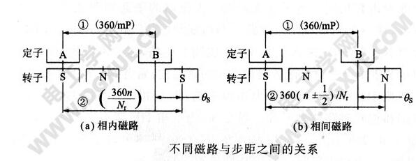
At this time, the pitch 2 of the rotor teeth of the rotor teeth opposite to the A phase and the second phase of the B phase are 360°n/Nr (n is an integer), and the step angle is a difference of 1 and 2:

Substituting the equation θs=180°/PNr into the above formula:
Nr=m(nP±1/2)
This is an expression of the rotor tooth Nr and the number of phases P and the number of main poles m in the case of the in-phase magnetic circuit. In the above formula, Nr must be an integer, otherwise it has no meaning. At this point, note that m must be an even number.
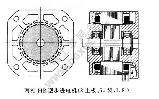
Two-phase HB type hybrid stepping motor, when P=2, the main pole 8 (m=4) is substituted into the above formula, which gives: Nr=8n±2
This is the relationship of the two-phase HB type hybrid stepping motor. The step angle of the two-phase HB type stepping motor is usually 1.8°, and n=6 is substituted into the above formula to obtain Nr=50.
The structure of the stator of the two-phase HB type hybrid stepping motor is 8 and the structure of the rotor teeth is 50 as shown in the following figure.
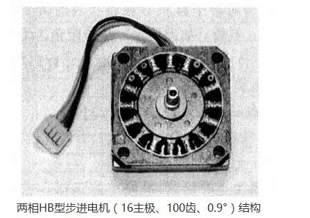
The two-phase HB type stepping motor has a step angle of 0.9°, the stator main pole is 16, m=8, n=6, and the structure of the rotor teeth is 100 as shown in the following figure.
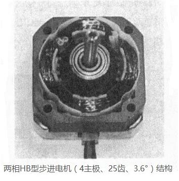
The two-phase 3.6° stepping motor stator main pole 4 (unbalanced electromagnetic force is generated between the stator and rotor, so the use of this structure is discouraged), according to the formula Nr=m(nP±1/2), when P = 2, When m=2 and n=6, Nr=25 is obtained. The small picture is two-phase, stator 4 main pole, 3.6 ° stepper motor structure, its shape is 42mm stepper motor, used for 5 inch 48TPI FDD (floppy disk drive). When it is a three-phase, by the formula Nr = m (nP ± 1/2), m = 4, n = 4, P = 3, and Nr = 50. The stator main pole number is mP=12, and the step angle θs is 1.2°.
Above: The relationship between different magnetic circuits and step size (b) is the phase-to-phase magnetic circuit, the stator pitch is equal, the total number of main poles is mP, and the pitch between adjacent A and B phases is 1 The phase of the magnetic circuit in the phase is the same, which is 360°/mP. Phase A is excited and relatively attracted to rotor teeth of opposite polarity. Secondly, the B phase excitation generates the same polarity as the A phase, attracting the corresponding rotor teeth. For ease of understanding, the multi-tooth structure is simplified to a single-tooth structure.
At this time, the pitch 2 between the rotor teeth opposed to the rotor teeth and the B phase with respect to the A phase is 360 (n ± 1/2) / Nr (n integer) as shown in the drawing. Therefore, the step angle is the difference between 1 and 2:

If the phase magnetic circuit is three-phase, let P=3, then:
Nr=m(3n±1)
In the case of three phases, the main magnetic pole is a multiple of 3, and in the simplest three-phase 3 main pole, m=1 becomes the following formula:
Nr=3n±1
The following figure shows the structure of n=3 and Nr=8. Using the above formulas Nr=3n±1 and θs=180°/PNr, Nr and θs can be calculated and calculated as shown in the following table.
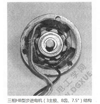
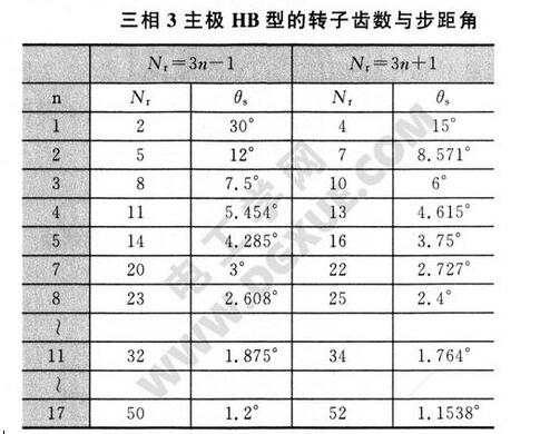
When designing, it should be noted that the three-pole HB type stepping motor will generate unbalanced electromagnetic force. Since only three coils are used, it is attractive for applications for low cost motors.
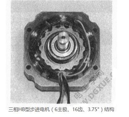
Three-phase, when the main pole of the stator 6 is m=2, the following formula is obtained: Nr=2 (3n±1). The structure of the motor with n=3, Nr=16 and step angle 3.75° is shown in the figure below.
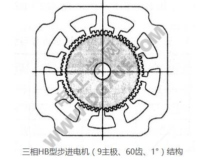
For three phases, when the main pole of the stator 9 is m=3, then Nr=3 (3n±1). The motor with n=7, Nr=60 and step angle 1°, the axial section is shown in the figure below.
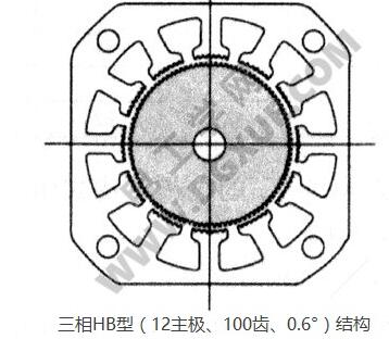
Three-phase, when the main pole of the stator 12 is m=4, then Nr=4 (3n±1). The axial sectional view of the stepping motor with n=8, Nr=100 and step angle 0.6° is shown in the figure below:
The above briefly introduces the relationship between the phase number, the number of main poles and the number of teeth of the HB type hybrid stepping motor in the phase magnetic circuit and the phase magnetic circuit. Not only do you need to understand these basic principles when designing a motor, but you also need to know the structure, performance, and dimensions of the motor when using the motor, and you can introduce the internal structure of the motor and solve the problem based on the phase number and step angle.
High voltage ESS ,HV battery,outdoor,large scale battery,one-stop solution provider for energy storage, high voltage battery ,high voltage battery storage system,outdoor high voltage battery cabinet
Shenzhen Enershare Technology Co.,Ltd , https://www.enersharepower.com