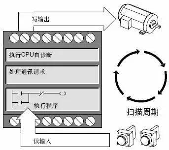
The CPU self-test phase includes a CPU self-diagnostic test and a reset watchdog timer.
In the self-diagnosis test phase, the CPU detects the status of each module of the PLC, diagnoses and processes the fault immediately, and gives a fault signal to illuminate the LED indicator on the CPU panel. When a fatal error occurs, the CPU is forced to STOP mode and execution of the program is stopped. The self-diagnosis test of the CPU will help to detect or predict the failure of the system in time and improve the reliability of the system.

The watchdog timer, also known as the watchdog timer WDT, is a hardware clock inside the CPU that is set to monitor each scan time of the PLC. Set the specified scan time before the CPU runs, and monitor the scan time to exceed the specified value for each scan cycle. This can avoid system failure due to the PLC entering an infinite loop during the execution of the program, or the system failure due to the PLC executing an unscheduled program. If the program is operating normally, the WDT is reset (cleared) during the internal processing phase of each scan cycle. If the program runs out of order and enters an infinite loop, the WDT will not be cleared on time and trigger a timeout overflow. The CPU will give an alarm signal or stop working. The use of WDT technology is also an effective measure to improve system reliability.
During the communication processing phase, the CPU checks for communication tasks, and if so, calls the corresponding process to complete communication with other devices (for example, intelligent modules with microprocessors, remote I/O interfaces, programmers, HMI devices, etc.). And deal with the communication data accordingly.
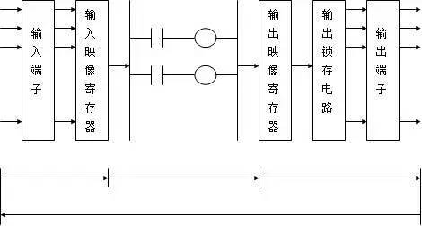
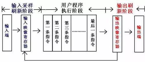
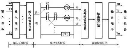
During the read input phase, the PLC scans all input terminals and stores the on/off status of each input into the corresponding input image register, refreshing the value of the input image register. Thereafter, the input image registers are isolated from the outside world, and the contents of the input image registers do not change regardless of changes in peripheral input conditions. Changes in the state of the input can only be picked up during the read input phase of the next cyclic scan cycle. This ensures that the same input signal state is used in one cycle scan cycle. Therefore, it should be noted that the width of the input signal is greater than one scan period, otherwise it is likely to cause signal loss.
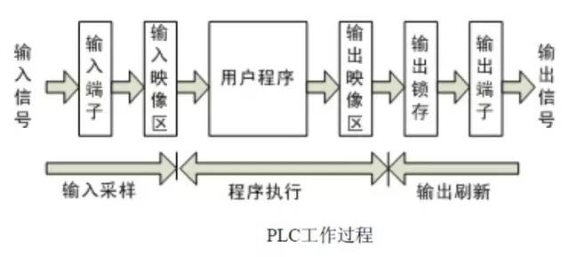
The user program of the programmable controller consists of several instructions, which are arranged in memory in order. When the PLC is in the run mode execution program, the CPU scans the user program in order. If the program is represented by a ladder diagram, the program instructions are executed one by one in order of up, down, and left to right. Each time an instruction is scanned, the state of the desired input signal is read from the input image register instead of directly using the on/off status of the field input terminal. During the execution of the user program, the corresponding operation or processing is performed according to the instruction. The result of each operation is not directly sent to the output terminal to immediately drive the external load, but the result is first written into the output image register. The value in the output image register can be used by subsequent read instructions.
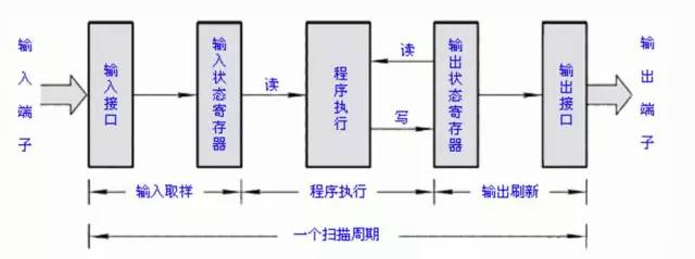
After executing the user program, enter the refresh output stage. The programmable controller sends the on/off status in the output image register to the output latch, and drives the user output device or load through the output terminal to implement the control function. The value of the output latch is held until the next refresh output.
After the refresh output phase is over, the CPU enters the next cyclic scan cycle.
1.00Mm Pin Header Connector,1.00Mm Smt Vertical Connector,1.00Mm Smt Vertical Type Header Connector,1.0Mm Prone Sticker Type Connector
Shenzhen CGE Electronic Co.,Ltd , https://www.cgeconnector.com