Ok, now let's talk about the distortion of the pwm waveform through the pc817b optocoupler.
As shown below:

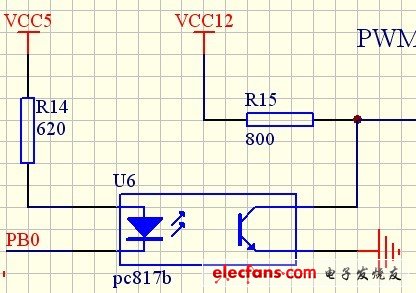
Circuit diagram after distortion after optocoupler


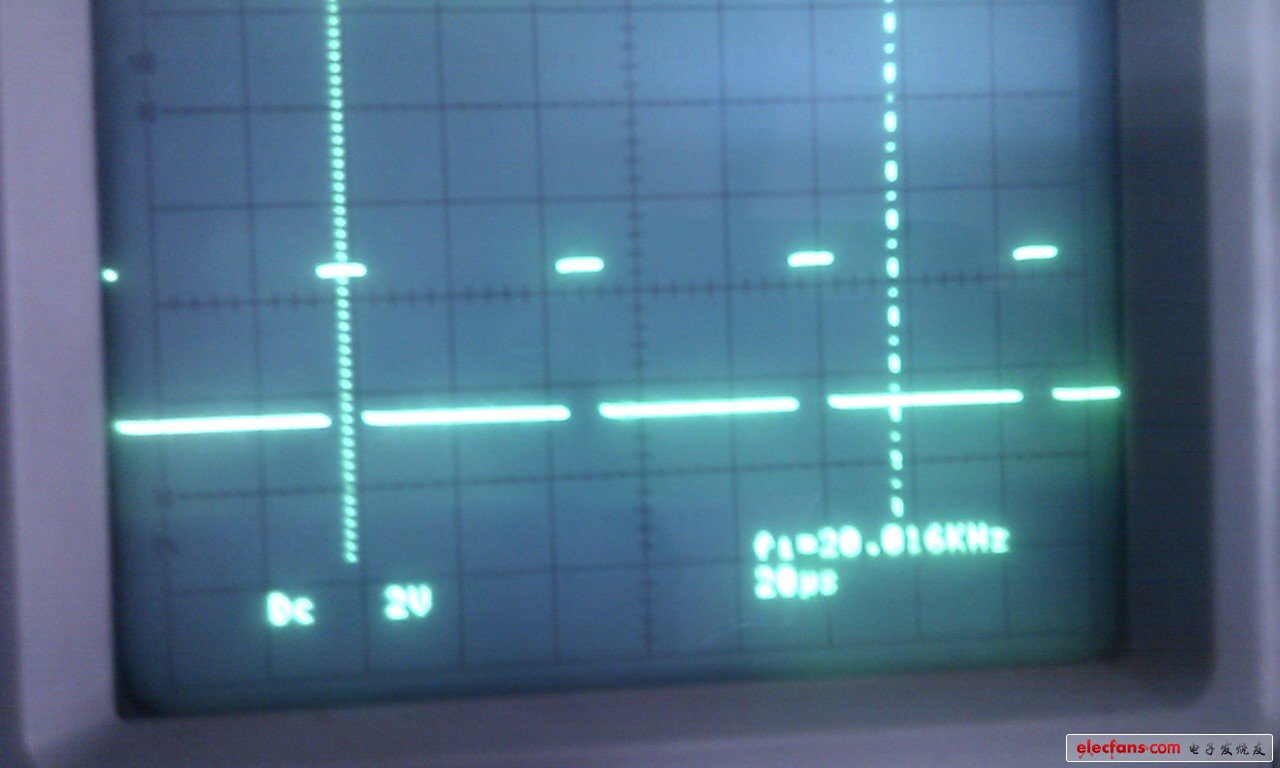
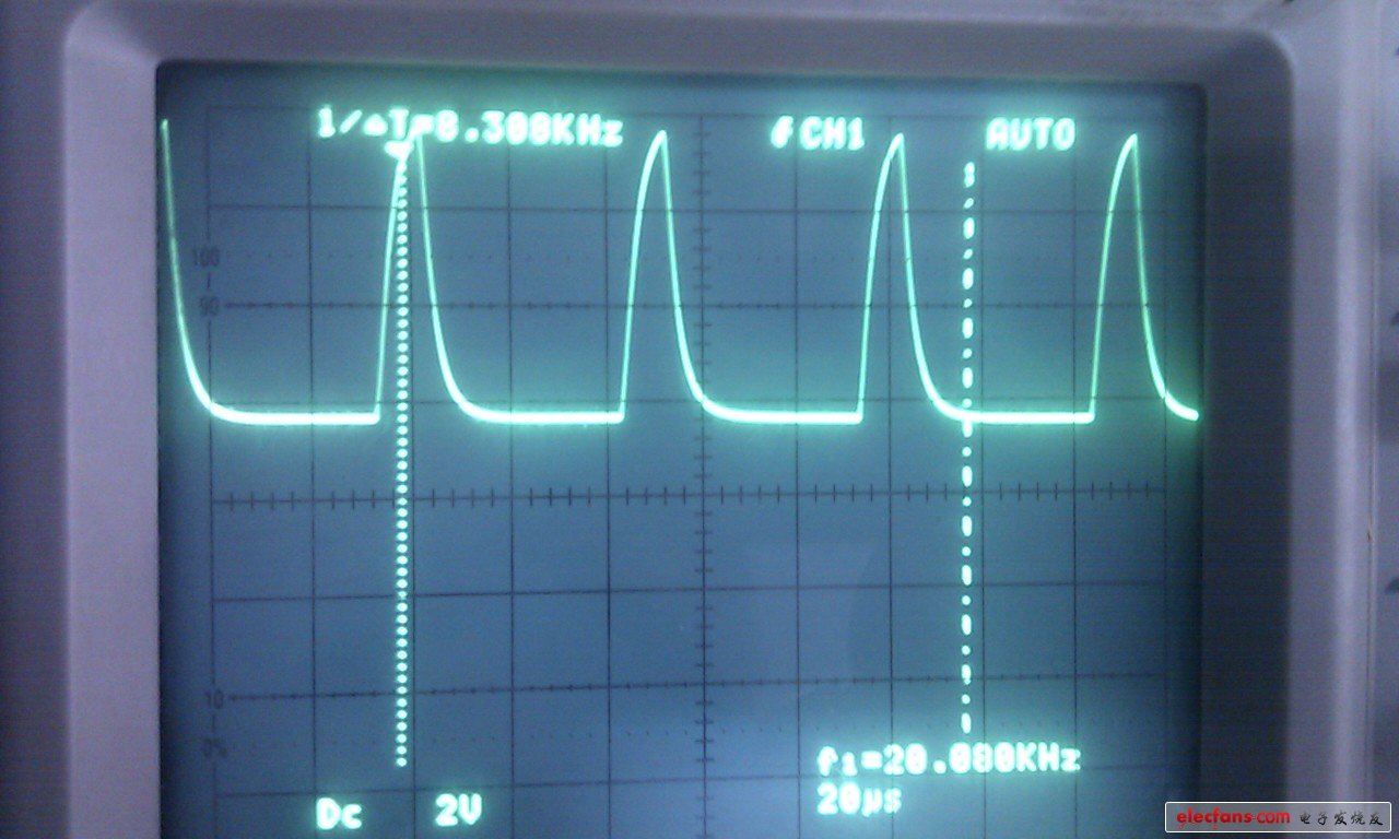
Waveform after distortion after optocoupler
Ok, the above is the question, now we begin to discuss and teach you to analyze ideas.
The first step: look at the PC817B data sheet to see if the frequency PWM frequency is exceeded.
The second step: As shown in the above waveform diagram, at 20K, the voltage gain is significantly reduced in the frequency response diagram, so you can also verify it and try to reduce the frequency.
The third step: 20khz wants to be basically undistorted, you can change the 1M optocoupler.
Step 4: Please pay attention to the minimum value of the current transfer coefficient CTR. You can calculate the current input Iin and the maximum current Iout = Iin * CTR. According to the above calculation, your circuit can't drive 12V/800 ohm circuit. You can change R14 to 200 ohms, then try again.
Actual debugging effect:
Replace R14 with over 300 ohms, and there is basically no output signal at 300 ohms.
Reduce the frequency to 2k, basically no distortion, it seems that the frequency is too high.
Peripheral discourse:
As shown below:

Circuit diagram after distortion after optocoupler


Waveform after distortion after optocoupler
Ok, the above is the question, now we begin to discuss and teach you to analyze ideas.
The first step: look at the PC817B data sheet to see if the frequency PWM frequency is exceeded.
The second step: As shown in the above waveform diagram, at 20K, the voltage gain is significantly reduced in the frequency response diagram, so you can also verify it and try to reduce the frequency.
The third step: 20khz wants to be basically undistorted, you can change the 1M optocoupler.
Step 4: Please pay attention to the minimum value of the current transfer coefficient CTR. You can calculate the current input Iin and the maximum current Iout = Iin * CTR. According to the above calculation, your circuit can't drive 12V/800 ohm circuit. You can change R14 to 200 ohms, then try again.
Actual debugging effect:
Replace R14 with over 300 ohms, and there is basically no output signal at 300 ohms.
Reduce the frequency to 2k, basically no distortion, it seems that the frequency is too high.
Peripheral discourse:
6N137 is about 1.8 yuan
4N25 also costs about 1 yuan
PC817 only needs about 1.5 hair.
Think about it, a penny of goods, PC817 as long as 1 hair 5, no distortion is strange.
Everyone continues to discuss, give people who pass by more ideas, good technology and good advice.
Everyone continues to discuss, give people who pass by more ideas, good technology and good advice.
Product Brand:SnCu0.7.SnCu0.3.SnCu3.SnAg0.5Cu0.5.SnAg3Cu.SnAg4Cu.Sn Cu1Ag.
SnCu4Ag1.Sn Cu6Ag2.Sn Sb5
The drafter of lead free solder national standards of GB/T20422-2006.
The drafter of soft solder test method national standards of GB/T28770-2012.
The drafter of lead free solder-chemical composition and type industry standards of SJ001-2007.
Lead Free Solder Wire,Rosin Core Solder,Flux Core Solder,Low Temperature Solder
Shaoxing Tianlong Tin Materials Co.,Ltd. , https://www.tianlongspray.com