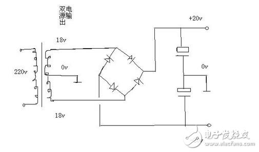
No two rectifier bridges are needed. Use one, connect two 18 volt AC to the AC input of the rectifier bridge, connect the transformer tap 0 volt ground wire (the ground wire of the circuit board), the rectifier bridge DC output + - the termination capacitor filter, and the capacitors are connected in series. After that, the positive pole is connected to the positive pole of the rectifier bridge, the negative pole of the capacitor is connected to the negative pole of the rectifier bridge, and the middle of the two capacitors connected in series leads out a line grounding wire, that is, a double 18 volt AC tap. This allows a dual supply of plus or minus 20 volts to be obtained at the DC output.
The circuit is as shown:

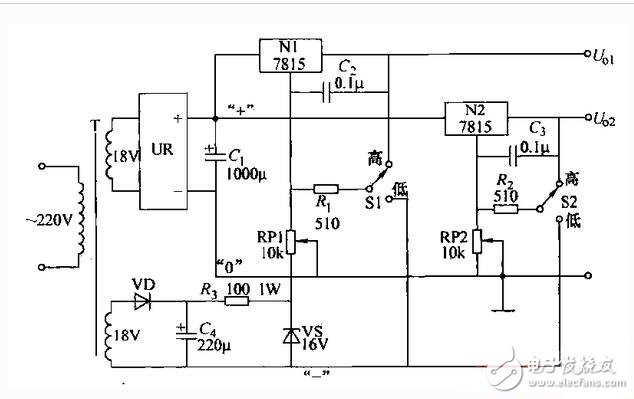
The dual voltage adjustable regulated power supply line shown can be used as a power source frequently used in line experiments. The current does not exceed 1A, but the two sets of voltages are adjustable and do not affect each other. Nl and N2 are 78 series three-terminal regulator integrated circuits. Since the output voltage is equal to the sum of the nominal regulation value and the common ground terminal voltage, it is only necessary to add an adjustable positive and negative voltage to the common terminal. The output voltage is adjustable. The lines N1, N2 share a set of rectified power supplies. The other set of output of the transformer T, after VD rectification, C4 filtering, 焉 current limiting, VS voltage regulation, provides a common reference negative voltage, and the polarity of the voltage applied to the common terminal can be selected through the switches S1 and S2, and then Adjust RP1 or RP2 to adjust the two output voltages separately. According to the data shown in the figure, the two output voltages can be continuously changed in the range of 1.5 to 25V, and the voltage stability also meets the requirements for use. When the voltage is turned down, the input/output voltage difference of the integrated circuit is large, and the power consumption is correspondingly increased, so the heat sink must be mounted. In addition, when the positive reference voltage is selected, the closer the slider of the potentiometer is to the ground end, the higher the output voltage, and when the negative reference voltage is selected, the output voltage is lower when the sliding arm is close to the ground. The selection principle of RP1 and RP2 is to make the voltage regulation value slightly higher than the nominal value of the integrated circuit. The maximum input/output voltage difference of the voltage regulator circuit generally does not exceed 35V. Therefore, the secondary side voltage of the transformer should not be higher than 25V to avoid damage to the integrated circuit.

Because thyristors are cheap and mature, relying on transformer technology is now doing very well.
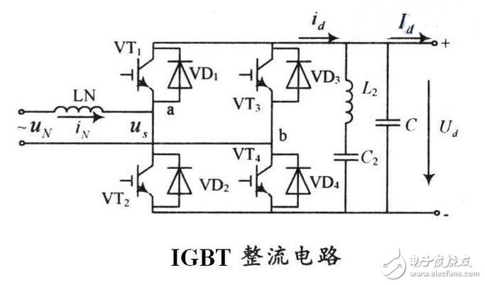
2. The current current of IGBT can't be done very much, and the parallel technology is still not enough in China. The price is high.
There are not many foreign countries that are doing IGBT rectification now.
There are the above reasons. Also, the IGBT trigger uses a high-frequency output that also exhibits a high-frequency pulse type, and the filtering requirement is high. If the trigger does not use a high frequency, the control performance is very bad. The thyristor (thyristor) is a semi-controlled component. After the trigger is turned on, the waveform is continuous, the control is relatively easy, and the filtering requirement is also easy. Therefore, under normal circumstances, it is necessary to use rectifiers for rectifiers and IGBTs for inverters.

The high-current slip ring is specially developed for high-power equipment. It can choose 50A, 100A, 250A, 500A, 1500A, 3000A and other specifications. It can also combine current and signal, which is easy to install, light weight and large current load. It is very suitable for welding, electroplating and other industries.
High Current Slip Ring,Encoder Servo Motor,Connector Electrical,Rotating Electrical Connectors
Dongguan Oubaibo Technology Co., Ltd. , https://www.sliprobs.com