The echo (Echo) mentioned in this article refers to the echo generated by voice communication. That is, the words spoken by oneself when they are called and heard from the other side are heard by themselves. Echoes are available on both fixed and mobile phones. Hours can be tolerated, and when they are large, communication and communication are seriously affected. It is one of the important factors that affect voice quality. Some of my friends may have asked why I did not hear my own echo when I called. It was because the echo of mature products on the market was eliminated.
Echoes are classified into line echo and acoustic echo. Line echoes mainly exist in fixed lines because of echoes introduced by 2-4 line conversions. Acoustic echoes are echoes generated by spatial acoustic reflections. Echo canceller (EC) is an important part of speech preprocessing. The following mainly describes its basic principles and some experience in debugging.
1, the basic principle
1) Adaptive filter and adaptive algorithm
In general, the coefficients of the filter are fixed, and the coefficients of the adaptive filter are changed, and the filter coefficients are adjusted according to the adaptive algorithm. The structure of the adaptive filter can be either FIR or IIR. Due to the stability of the IIR, FIR is generally used.
The following figure shows the general structure of an adaptive filter:
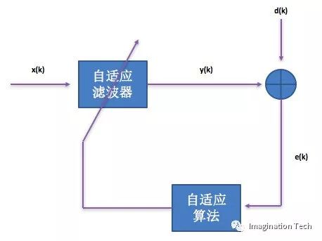
In the figure above, x(k) is the input signal, y(k) is the output signal, d(k) is the desired signal, and e(k) is the error signal of d(k) and y(k). The filter coefficients of the adaptive filter are controlled by the error signal e(k) and automatically adjusted according to the value of e(k) and the adaptive algorithm.
Adaptive algorithms generally use the least mean square (LMS) algorithm and its variants (such as the NLMS algorithm). The LMS algorithm is a member of the stochastic gradient algorithm family. Specific can see related articles.
2) The basic principle of echo cancellation.
The following figure is a block diagram of the basic principle of echo cancellation:
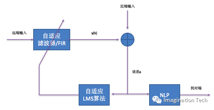
The process is as follows:
a) Calculate the energy of the near-end far-end voice data to determine if the two parties are silent or talk.
b) After the remote input has passed the adaptive FIR filter, it has obtained data similar to the near-end input, and has been subtracted from the near-end input to obtain the error e. The error e is used as the input of the adaptive LMS algorithm to update the coefficients of the adaptive FIR filter when needed, for later processing of the far-end data. When it is needed, it refers to the case where the remote talk is near-end silent. In other cases (such as double silent / double talk), there is no need to update the coefficients of the FIR filter.
c) The error e will also produce comfortable noise after the NLP (non-linear processing) is sent to the other party.
2, debugging
EC is relatively difficult and it is not easy to do well. Before webRTC open source, it was mainly large companies and professional algorithm companies that had a good implementation plan. In general, companies would like to buy an algorithm library if they have EC. Some core algorithms (including AEC/ANS/AGC, etc.) are also open source after webRTC open source, so that companies start to use webRTC algorithms, especially Internet companies, AEC and other algorithms are basically used webRTC.
I have two EC debugging experience. The first time was at the chip company, doing voice solutions. The echo cancellation implementation from the company's algorithm department was used to apply it to the solution. Another time is in the mobile Internet company, to do real-time voice communication APP, to use webRTC AEC to APP. The first time spent more, to learn the principle, look at the algorithm code, do the application verification algorithm and to modify the coefficients, debugging on the product. The second time, with the first base plus the webRTC package, it took less time. Personally think that there are basically a few steps to debug on the basis of EC zero-based but existing EC algorithm code:
1) The basic principle of learning echo cancellation involves signal processing knowledge (from fixed coefficient filters to coefficient adaptive filters) and advanced mathematics knowledge (gradients). Because it is not an algorithm, it is enough to master the basics. If the foundation is solid, of course, the better you can do it, the better.
2) Look at the algorithm code. If there is an implementation of the design document that is the best, a lot of algorithm implementation techniques, there is a design document can better understand the code. Nothing can only bite the bullet. At first it may be that some people don't understand it and look at it several times. Maybe they will know more about each time.
3) Be an application verification algorithm. The application input is a near-end and a far-end PCM file. Write the output of the EC into a PCM file to see how well the process works. This can also be divided into small steps:
a) Set the latency to zero, the same for the near and far end PCM files, and theoretically the output is all zero data. If so, congratulations on the algorithm you choose has a good base. If it is not, then you need to adjust some of the coefficients in the algorithm. This may be adjusted several times. The final result of the debugging is that the output of the algorithm is basically inaudible.
b) Set a certain latency. The near-end PCM is the same as the far-end data, but the near-end PCM data has a certain delay relative to the far end. This value is the same as the set value of the latency. At this time, the theoretical output is Or all zero data.
c) Acquiring near-end and far-end PCM data on the actual product, you can approximate the proximal and distal latency. Take these as input, see the output of the algorithm, but also basically can not hear the echo. After this step is adjusted, the algorithm can basically be used.
4) To adjust on a specific hardware platform. The latency is not the same on every hardware platform. There is a demo board at the chip company. Each customer also has their circuit board. The hardware platform is relatively small. One can access the far-end PCM data to adjust the latency. When mobile Internet companies do apps, there are many types of mobile phones and they are too tired to use the above method. Then a slider is set on the UI to configure the latency, so that testers can test to find a relatively good latency and put it in the configuration file. Save it, later this phone will use this value of latency.
After the above steps, the EC debugging on the real product is finished.
The stadium LED screen is ideal for places of with huge crowd. Its high resolution picture and wide viewing angle ensure best quality pictures and videos to every corner of the stadium. Stable body protects the display from any damage, even high speed ball.
The LED Display is manufactured by using best quality material, purchased from most reputed vendors. The final products feature supreme quality and offers best outputs. High refresh rate and gray scale ensures the picture quality remains seamless.
The display features a wide viewing angle of 120° horizontal and 120° in vertical which reaches more viewers. The picture quality remains seamless in all direction and at a distance, presenting all viewers the same highly quality outputs. This makes it suitable for large gathering. -
Stadium LED Display,Football Led Display,Staduim Led Display,Outdoor Football Led Display
Guangzhou Chengwen Photoelectric Technology co.,ltd , https://www.cwledpanel.com