The 3021 Series LED Power Modules differ from standard power modules that output a fixed voltage. Their output voltage can be adjusted as needed, and the output constant current can drive high-power LuxeonI (350mA), LuxeonV (700mA) and LuxeonIII (lOOOOmA) LEDs. Or LED string. 3021 series LED power modules can be widely used in solar landscape lighting, architectural lighting, small road lighting, automotive and marine lighting, portable lights, flashing lights, shopping spot lighting, table lamps and reading lamps, signal and sign lighting, cabinet and showcase lighting, instructions Cards and route text and symbol lighting.
Package and pin function
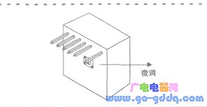
figure 1
The 3021 Series LED Power Modules from LuxDrive offer a simple 7-pin SIP connection or an optional wiring harness for through-hole printed circuit board mounting. Figure 1 shows the outline of the series of 7-pin SIP packages (the actual output pin is 6), the size is 20.96mm × 20.96mm × 11mm, the lead length is 5.84mm, and the lead diameter is 0.762mm. The names of the pins of the 3021 series power module are shown in Figure 2. The functions of the pins of the 3021 series module are: LED+ is the positive output. Connect external LED anode; LED- is negative output, connect external LED cathode; CTRl is control terminal; Ref is 5V reference voltage output terminal: Vin+ is power supply voltage positive input terminal; Vin- is power supply voltage negative input terminal.
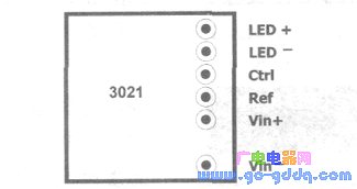
figure 2
main feature
The main features of the 3021 series LED power module are as follows: (1) The DC input voltage range is 5~32V, and three modules can also input AC voltage (range 7~24V): (2) output constant current is 350mA, 500mA, 700mA and 1A four specifications; (3) package with a very small form factor (0.83" x 0.83" x 0.43"), providing a simple 7-pin SIP connection for through-hole PCB mounting with optional wiring harness The device can also be used: (4) external analog / digital brightness control (TTL compatible), optional external potentiometer brightness control (range 0 ~ 100%) and optional on-board output current fine-tuning (range 40 ~ 110) (5) Built-in 5V reference, which provides a stable output as a power supply for the logic circuit or microprocessor, thus removing the additional power supply circuit: (6) The fast response current sensing circuit supports LED flash or strobe operation: (7) Provide output open circuit and short circuit protection; (8) In the application, it can drive single LED or multiple LED strings without any external components. The maximum output power can reach more than 30W and the efficiency can reach 95%. (@DC input is 5V).
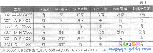
The 3021 series modules are available in six models, as shown in Table 1.
Application circuit
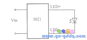
image 3
1. Fixed current drive circuit 3021 The module drives a single LED circuit as shown in Figure 3. If the LED model is LuxeonV, the 700mA module should be used (and the input DC voltage should be no less than 12V); if the LuxeonI LED is driven, the 350mA module should be used; if the LED is NIChi-a Jupiter, Use a 500mA module; if the LED is Luxeon..., use a 1000mA module.
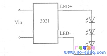
Figure 4
The 3021 module can directly drive three LEDs connected in series, as shown in Figure 4. If the LED is Luxeon III, a 1000 mA module should be used. Since the forward voltage drop VF of this type of LED is about 3.5V, the sum of the forward voltages of the three LEDs is 10.5V, so the input DC voltage VIN ≥ 12V is required. In Figure 4, if the LED is LuxeonV, a 700mA module should be used. Since the forward voltage drop of LuxeonV is much higher than that of Luxeon III, VIN ≥ 24V is required.
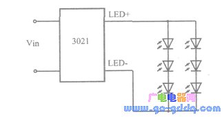
Figure 5
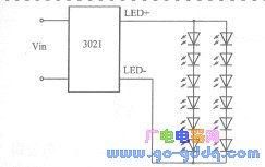
Figure 6
Figure 6 and Figure 7 show the circuit for driving two parallel LED strings consisting of LumiLEDs using a 700 mA 3021 module, respectively, and requiring DC input voltages VIN of not less than 12V and 24V, respectively. Figure 7 shows a circuit in which the 1021 mA 3021 module drives three parallel LED strings of nine Lux ~ eonI. In this drive circuit, VIN ≥ 12V is required.
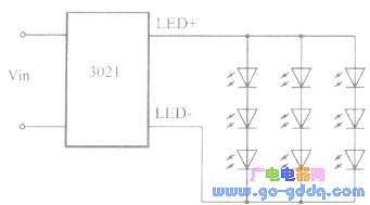
Figure 7
2, adjustable current drive circuit "I" model (referring to the letter I in the model) power module output current can be adjusted by the on-board potentiometer, the adjustment range is 40% ~ 110% of the current rating.
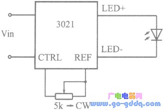
Figure 8
The "E" model power module can regulate the output current through an external potentiometer, as shown in Figure 8 and Figure 9. In Figure 8, a 5kΩ linear potentiometer is connected between the 3021 module 5V reference output (REF) and the control terminal (CTRL), requiring VIN > 5.25V; in the following figure; using a 5V external power supply for a 5K potentiometer Power up. In both circuits, the current through the potentiometer is less than 5 mA, and a small power potentiometer can be used. The output current is adjusted by an external potentiometer, and the brightness adjustment range of the LED is 0 to 100%.
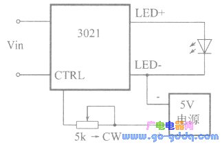
Figure 9
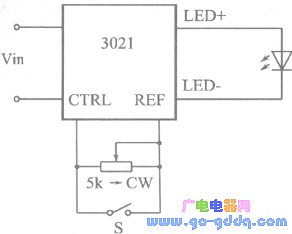
3. Control method (1) External on/off control: In the circuit, the on/off control adopts manual button or transfer switch. When the switch is closed, the output of the 3021 power module is turned off, and the LED is extinguished due to no current passing. The circuit shown in Figure 11 uses a logic level input to perform the on/off control. When the logic low level is input, the module is turned off. Both of the circuits of Fig. 10 and Fig. 11 are based on the current regulating circuit shown in Fig. 8, thereby realizing both external dimming and on/off control functions.

Figure 10
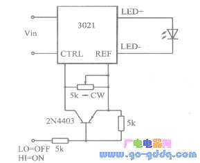
Figure 11
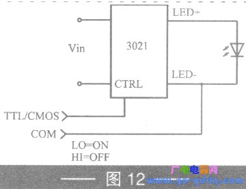
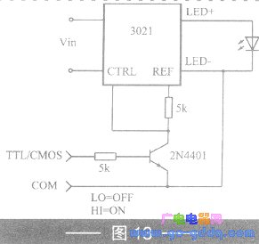
(2) External Pulse/Flash Control: Figures 12 and 13 show two methods of low speed pulsation and high speed flash operation, respectively. In Figure 12, a TTL/CMOS signal is added directly to the control input (CTRL) of the 3021 module. When the logic signal is at a high level of 5V, the output current will be zero. The circuit shown in Figure 13 is the opposite. When the input signal is at a high level of 5V, the module output is turned on. In the two circuits shown in Figures 12 and 13, the module output signal rise and fall times are no longer than 15μs, and the input pulse frequency can reach 10kHz.
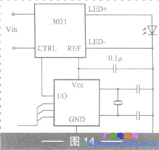
(3) Microprocessor control: Figure 14 shows a typical interface circuit of a microchip PIC or similar microprocessor. The interface output provides the microprocessor with an operating voltage of 5V and a maximum current of 20mA.
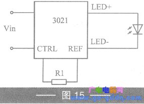
(4) Other control scheme: Connect a resistor R1 between the control terminal of the 3021 module and the reference voltage output terminal to reduce the output current, as shown in Figure 15. The output fixed current value depends on the R1 value, the percentage of the rated current is equal to (Rl/50) × 100%, and the unit of R1 is kΩ.
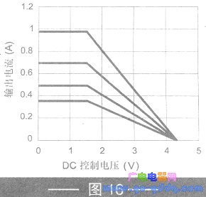
The 3021 power module can also be driven by a D/A converter. Figure 16 shows the effective control range of the analog input signal.
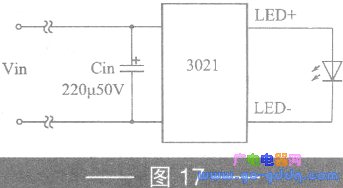
When the DC power supply to the module is more than 18 inches away, a 220μF/50V capacitor should be connected between the two power line inputs, as shown in Figure 17.
PTC Thermistor for Overcurrent Protection for Telecom
PTC Thermistor ,Thermistor,Thermistor for Overcurrent Protection ,PTC Thermistor YZPST
YANGZHOU POSITIONING TECH CO., LTD. , https://www.cnpositioning.com