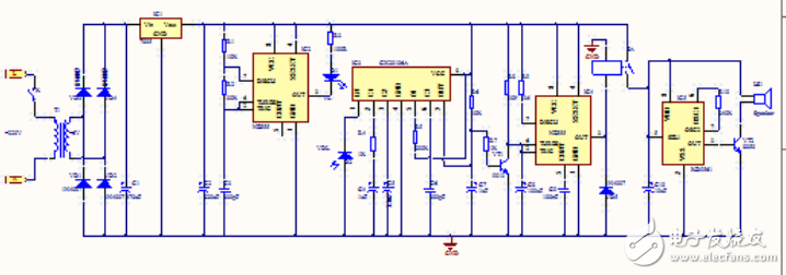
Circuit principle: The infrared emitter consists of IC2, R1, R2, C3 and other components to form a multi-vibrator with an oscillation frequency of 40 kHz. D1 is an infrared emitting probe whose 40 kHz high frequency signal radiates outward to form an infrared beam. The VDL is an infrared receiving probe. It and the IC3 (CX20106A) form an infrared receiving, shaping and amplifying circuit, and the amplified infrared signal becomes an electrical pulse signal. IC4 and its peripheral components form an alarm execution circuit. Once its 2 pin is low level, the circuit immediately flips, and the signal output terminal 3 immediately turns to a high level output, and has a delay function. Normally, the VDL receives the infrared beam of D1 radiation. Infrared receiving dedicated preamplifier integrated circuit (its feature is high sensitivity, no inductive resonant coil) IC3 signal output terminal 7 is low level, VT1 is off state, IC4 pin 2 is high level, 3 feet is Low level output, so the subsequent circuits will not work, no alarm sounds. When someone passes through the main passage of the anti-theft object, enters the door of the house or approaches the anti-theft object, it blocks the infrared light. At the moment of blocking, the 7-pin of IC3 immediately turns to the high level, so that the VTl is saturated and turned on, 2 feet. Immediately low level, so IC4 flips, 3 feet is high level, K is electrically connected, and the power of the analog sound alarm IC IC5 is turned on, and the speaker BL emits a loud alarm sound. At the same time, IC4 enters the delay phase, after about t seconds (calculation formula is t=1.1R8C8) time, IC4 is set to make the 3 pin turn low again, and the alarm sound stops. If the infrared light is blocked again, the circuit will work again.

12V Solar Charge Controller,60 Amp Power Solar Charging Controller,60A Solar Controller,Solar Charge Controller
GuangZhou HanFong New Energy Technology Co. , Ltd. , https://www.hfsolarenergy.com