In a high-speed serial circuit, where is the DC blocking capacitor placed? Some engineers' answers are nothing more than two things: put it on the driver or put it on the receiver.
Some people say that it is placed on the receiving end. The reason is: since the signal passes from the driving end to the receiving end through the transmission line, it will cause attenuation and the rise time will be prolonged. When the signal finally reaches the capacitance of the receiving end, most of the high-frequency components are gone. The reflection is reduced, so more signals can be sent to the receiving end. (Time Domain)
An SI engineer may tell you that for all passive links, all the elements in the link are mutually influential, and the entire topology is also related, regardless of whether the signal is forward or backward. Therefore, it doesn't matter what the capacitor is. (frequency domain)
In order to solve this problem, the problem is analyzed by a simple method using data in the time domain and the frequency domain. Take a simple topology as an example, including a short transmission line, a long transmission line, several vias, and a capacitor near one end, as shown in Figure 1 : 
Figure 1 Schematic diagram of a simple topology (DC blocking capacitor is close to the receiving end)
Creating each topology model requires a lot of work. In this case, we ignore the complex things and only use a simple lumped model to explain the concept. The theory used is the same as that of the exact complex model.
Figure 2 shows the RLGC parameters for a consistent, uniform, passive, and causal transmission line with a characteristic impedance of 50Ω , a loss angle of 0.0016 , a linewidth of 3mil , a DK of 3.9 , and a propagation delay of approximately 173ps at 1G . /inch .
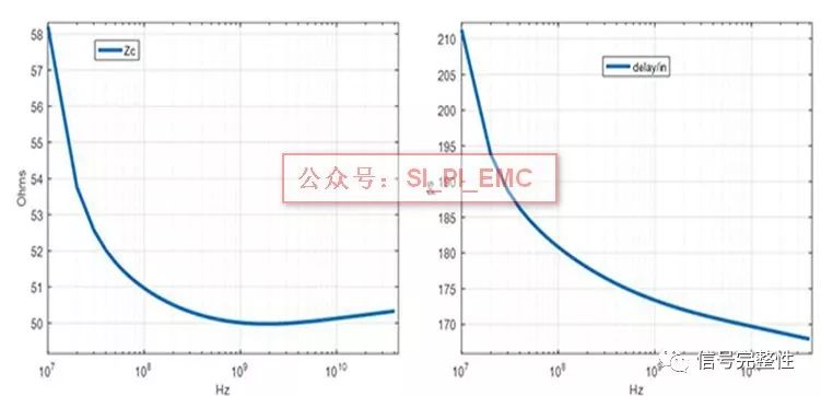
Figure 2 Transmission line impedance (left); transmission line delay (right)
The via is assigned to a simple 2pf lumped shunt capacitor model, as shown in Figure 3 :
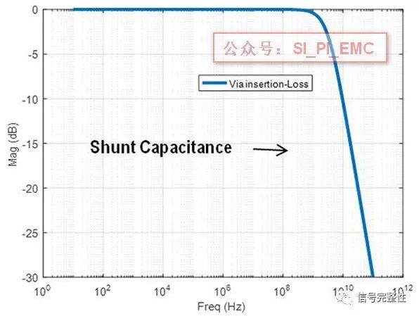
Figure 3 shows the parallel capacitor
Finally, the model of the capacitor assignment is a series RL , replacing the internal parasitic parameters, adding a shunt capacitor at each end and connecting it to the transmission line to indicate the pads and vias, as shown in Figure 4 .
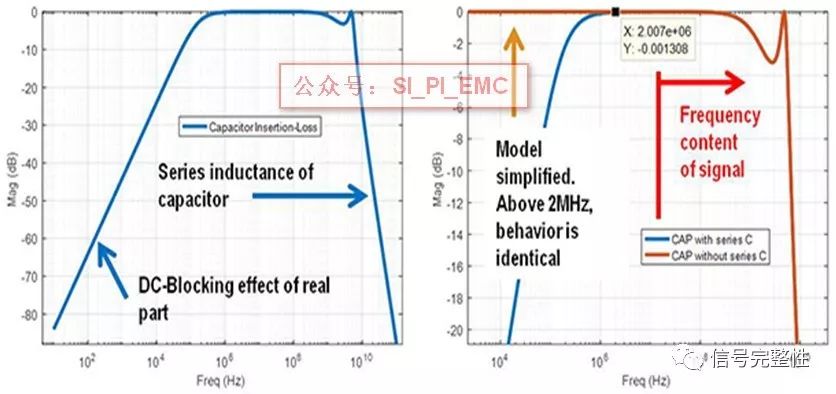
Figure 4
But for the capacitive model, the main series capacitor is removed, which helps to establish the simulated DC path and further TDR signal analysis. Even though this sounds a little weird, most high-speed signal protocols are DC balanced encoding below 100MHz . Above these frequency points, the model of adding series capacitance or short circuit at the appropriate position looks the same as in Figure 4 , and it is necessary to add parasitic inductance and current limiting capacitance at the frequency points of interest. After the various models are built, they are connected in series. Now to answer the questions at the beginning, as shown in Figure 1 , we need to consider two things:
a. Port-1 is the driver and Port-2 is the receiver (the capacitor is close to the receiver)
b. Port-2 is the driver, Port-1 is the receiver (the capacitor is close to the driver)
Port-1 at the input a pulse response observed in the Port-2, and then reversing (input signal on Port-2, was observed in response to the Port-1). If the first person is right, there will be a very large discontinuity in theory, then we should be able to see the difference in the waveform at the receiving end.
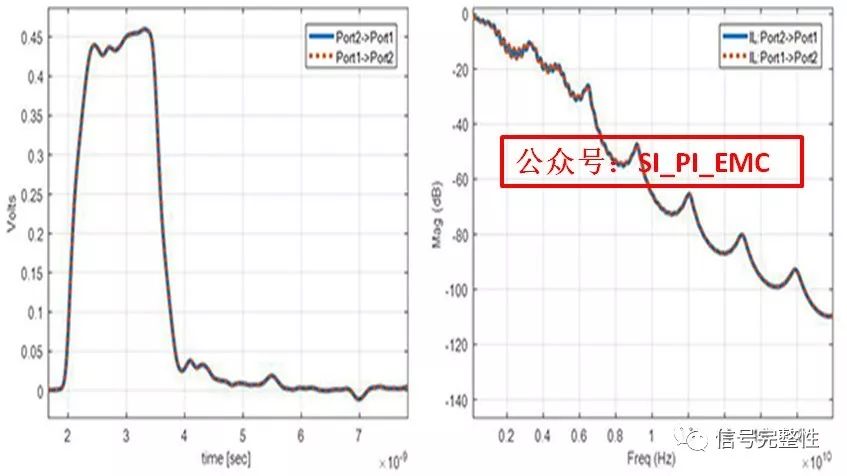
Figure 5 Time domain pulse (left); forward and backward loss (right)
The problem here is that the results in the two cases in Figure 5 are basically indistinguishable, meaning that for this topology and parameters, the capacitance has no effect on whether it is placed on the driver or receiver. So what about the second statement? The dependence of the S- parameter (for a two-port passive network, S21=S12 ), according to the result, the view of the time domain is wrong at this point, and the frequency domain view is correct. But let's take another analysis.
Figure 6 shows the return loss of the TDR and both ends. Through the TDR curve, each part of the topology can be clearly seen. Port-2 is close to the DC blocking capacitor and much larger than the TDR discontinuity of Port-1 . Similarly, Port-2 can be seen in the frequency domain . The loss is much worse than Port-1 .
Due to the asymmetry of the topology, S11 is not equal to S22 . It may be because this makes the position of the capacitor affect, but the fact is that in this simple example, the signal is transmitted forward or backward, as shown in Figure 5. Shown.
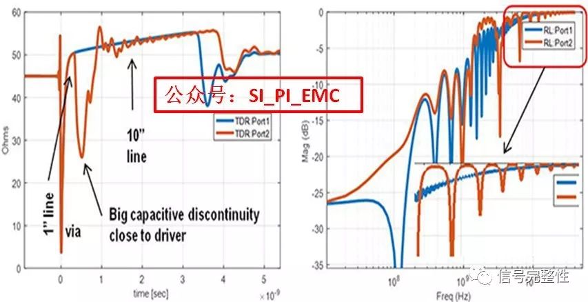
Figure 6 TDR curve (ports 1 and 2); return loss (S11 and S22)
So does the position of the capacitor have any effect? Now create a topology with a total length of 11 inches and move the capacitors from one end to the center in different increments. In theory we should not see the difference.
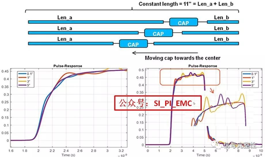
Figure 7: The rise time observed at the receiving end (left); the entire pulse waveform, magnified the reflection (right)
An interesting phenomenon can be seen in Figure 7. When the capacitor moves from the drive end to the middle of the transmission line, the following phenomena can be seen:
1. The signal at the receiving end has changed, proving that the capacitance is different at different locations on the transmission line.
2. However, when a position is determined, the signal generated at the receiving end is the same whether the drive is on the left or on the right.
3. When the capacitance is moved from the center position of the transmission line to both ends, the reflection pulse between the two ends can be observed at different times.
4. When the DC blocking capacitors are placed at each end, most of the bandwidth is on the rising edge, as shown in Figure 7 .
In fact, simply look at the position of the resonance, visually check the starting position of each resonance point, you can find the approximate position of the DC blocking capacitor at one end.

Figure 8 1/2 harmonic of each type of length
In Figure 8 , after calculation, the distance to one end is 1.3243 inches , which is approximately 1 inch . 3.06inch is approximately 3inch , 5.07inch and 6inch are approximately 5inch . Why are there two points that are approximately 5 inches ? When the capacitor is placed 5 inches from one end , it is also 6 inches from the other end because the total line length is 11 inches . At 5 inches , you can see the 1/2 harmonics on either side of the capacitor .
Of course these discontinuous pulses will continue to go back and forth several times until the natural loss of the transmission line attenuates it. When calculating the eye diagram, these points will interfere with subsequent parts, ultimately reducing the quality of the eye diagram at the receiving end.
So what if these more annoying resonances are there if there are more losses on the transmission line? Let's try it below.
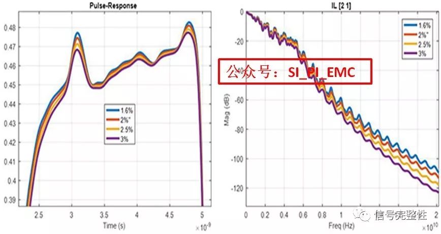
Figure 9 Resonance of each dielectric loss (left); loss (right)
By changing the dielectric loss angle in Figure 9 , it can be seen how the signal is generally reduced, but the same resonance point is small, and in many cases, the loss can be used to attenuate the resonance point.
After further testing, before the test, it is necessary to consider the input impedance of the driving source and the receiving end to be 50 Ohm , which is completely matched with the impedance of the transmission line. What happens if the capacitor is placed on the drive, and the source impedance is changed from 40Ohm to 50Ohm , while the receiver impedance is kept at 50Ohm .
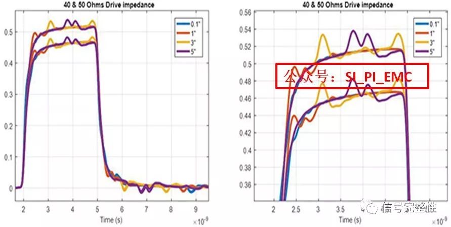
Figure 10 Results of 40 ohm and 50 ohm distal impedance
It can be seen from Fig. 10 that, as expected, the steady-state value of the voltage when the source impedance changes, but the size of the discontinuity point is not greatly affected as a whole, but it is not the discontinuity point of the source end and the capacitor. It won't change the amplitude of the signal, and it will eventually. The difference between the discontinuity of the transmission line and the discontinuity at both ends has a direct effect on the amplitude of the 1/2 harmonic mentioned above . In fact, due to the discontinuity of this value, the 1/2 harmonic is converted into a 1/4 harmonic.
In this particular example, the source impedance is 40-55 ohms, except that the high level in the pulse steady state changes as expected, and is substantially unaffected from the overall waveform.
Look at all the differential impedances of the capacitor at two different positions, as shown in Figure 11 , it can be seen that the main points affecting these points are the capacitance, not the impedance of the drive.
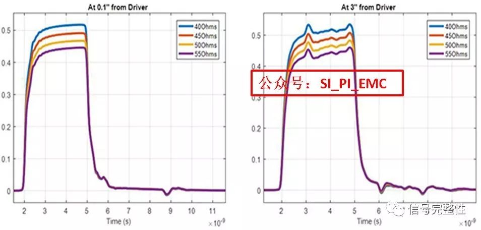
Figure 11 Add a capacitor at 0.1inch at the source (left); add a capacitor at 3inch at the source (left)
If you remove all the capacitors inside, the simulation topology above is symmetrical, meaning that there are the same number of discontinuities at both ends. The question is, what if the topology is not uniform? For example, if you have a connector near one end, or something else, to verify this problem, simply double the via at one end. Then run two examples at the same time, the first one is with a DC blocking capacitor, the distance to via4 is 10inch , and the distance between the second DC blocking capacitor and via4 is 1inch .
As can be seen from Figure 12 , the results of these two topologies are different from time to time and frequency domain. Blocking capacitor when the distance 4pf via (via4) closer reflection is relatively large. Don't think that the side of the capacitor with a large discontinuity is the worst choice. Probably not. It's hard to say that this applies to every situation, just depending on your topology and the type of discontinuity and how to use these discontinuities to place capacitance. The key is to try to place the capacitor by reducing the reflection, from the signal point of view, whether it is received or sent.
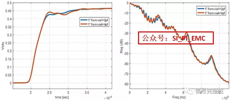
Figure 12 Step response (left); loss (right)
It is also important to consider other factors, such as detachable interfaces, hot swap, short circuit protection, etc., which will affect the placement of the capacitor. But from the perspective of SI , we can conclude that:
1. Â Â Â Â Â Â The placement of the capacitor should minimize the discontinuity of the transmission line. It is conceivable that the smaller the discontinuity of the capacitance, the smaller the reflection produced.
2. Â Â Â Â Â Â The overall capacitance should be closer to the driving end or the receiving end, and the distance is preferably less than 1/2 of the length of the UI , which is beneficial to reduce the influence on the eye diagram and avoid the reduction of the eye margin.
3. Â Â Â Â Â Â When the position of the capacitor is determined, do not consider the appearance of the topology. It does not matter which end is the driver.
Now let's look at the initial problem. It is true that we can say that both are correct: the capacitor does not matter (from the time domain perspective), but when we determine the topology, we no longer know where the driver is. As long as it is close to the driver or sender (frequency domain) .
9H Flexible Glass Screen Protector
This kind of Flexible Glass Screen Protective Film is made of nano-glass material and is an indispensable device for people who often drop their mobile phones. The Flexible Protective Film can be perfectly fixed on the mobile phone to completely protect the mobile phone screen to prevent scratches and cracks on the edge of the mobile phone screen.
The surface hardness is 9H hardness. Sharp objects (such as knives and keys) will not scratch the surface.
The high transparency of 0.22mm ensures that you can view all screen content clearly and clearly, while providing unique touch screen sensitivity.
The Screen Protection Film has an "oleophobic and waterproof" coating that prevents dust and fingerprint smudges and ensures that it can be easily removed.
In case the screen is damaged, the Screen Protector will break into small pieces that are not sharp, which is much safer than other glass screen protectors on the market.
If you want to know more about 9H Flexible Glass Screen Protector products, please click product details to view the parameters, models, pictures, prices and other information about 9H Flexible Glass Screen Protector products.
Whether you are a group or an individual, we will try our best to provide you with accurate and comprehensive information about 9H Flexible Glass Screen Protector!
9H Flexible Glass Screen Protector, 9H Screen Protector, 9H Flexible Protective Film, Flexible Protective Film
Shenzhen Jianjiantong Technology Co., Ltd. , https://www.jjthydrogelmachine.com