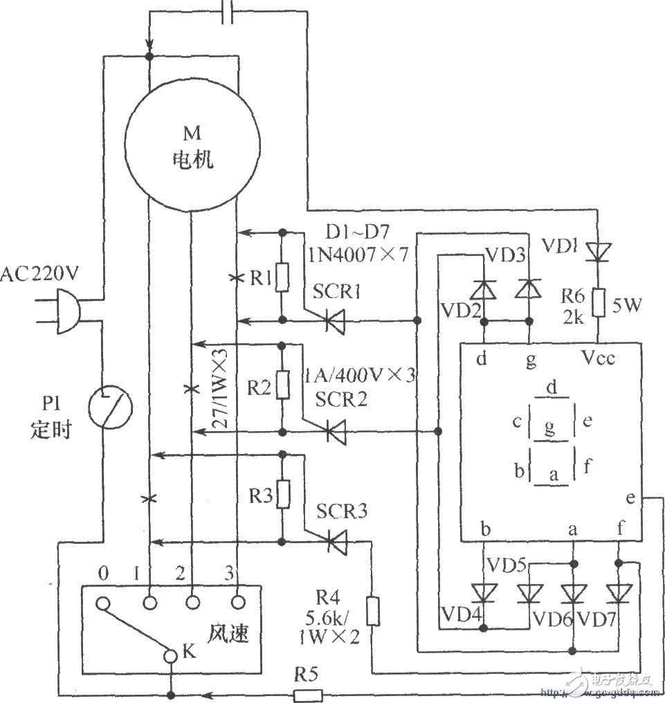
Generally, the speed control switch of an electric fan is printed with a "0~3" block word mark, which makes it difficult to see clearly when the distance is a little far away. The following introduces a simple and easy-to-make LED digital display circuit, which can make the wind speed gear of the electric fan intuitive and clear.
The working principle circuit is shown in the figure below, disconnect the original fan motor winding wind speed adjustment line with "x" in turn, and connect the voltage drop resistors R1 to R3. When the wind speed switch K is selected a certain gear, its corresponding winding loop current produces a voltage drop (voltage) on the corresponding resistance. This voltage immediately triggers the thyristor SCR to be turned on, and the current after it is turned on will supply power to the corresponding pen segment of the LED digital tube through VD2~VD7, etc., and the gear number can be displayed at this time. When the gear speed control switch K is switched, the original winding circuit is cut off, other winding circuits are connected, the thyristor controlled by the circuit is triggered, and the LED digital tube is driven to display the new number again.

Component selection: LED digital display tube should use common anode tube. SCR1~SCR3 choose 1A/400V thyristor. Select 1N4007 for VD1~VD7. Other components are selected as shown in the figure.
It is not necessary to make another printed circuit board during production and debugging. You can find a small experimental board instead. After installation, the lead wire and the original fan circuit can be directly connected at the place marked with an arrow (â†). Then, choose an appropriate position on the fan shell, use a tool to open a hole with the same size as the surface of the LED digital tube, insert the digital tube neatly, and finally fix it on the back with hot melt glue.
6.35MM Power+ Signal Power Connector
power connector is used in power module system. It can select the matching power + signal connector according to the need. The feature is that the number of power and signal contacts and the matching sequence can be selected arbitrarily while keeping the connector size and contact core number unchanged.
Plug (male) / socket (female) can be installed at 90 or 180 degrees. It supports mixed or independent combination of signal and power. The quantity range of power and signal is (2-16) pin and (12-128) pin respectively
Product features
High temperature resistant, glass fiber reinforced and flame retardant polyester is used as insulation material
Copper gold composite conductor with high conductivity is used, and the contact area of the conductor is plated with gold
It adopts shrapnel contact, which has the characteristics of integration, small volume, large current carrying capacity, soft plug-in, blind plug-in, self guidance and high dynamic contact reliability. This series of products can be interchanged with FCI's powerblade series and Tyco's multi-beam series
There are three sizes of center distance of power contact: 5.08mm, 6.35mm and 7.62mm
The length of power hole / signal pin can be selected in two sizes. The power rated current is 45A and the signal rated current is 2.5A
6.35MM Power+ Signal Power Connector
ShenZhen Antenk Electronics Co,Ltd , https://www.antenksocket.com