Step 1: Read the product manual.
The first step seems to be simple. Many equipment engineers will say that I have been responsible for this equipment for many years. Maintenance is done every day. There is no unfamiliarity. It is a waste of time to read the manual. Haha, this is a common problem for many engineers in China. Many people buy it from the equipment until they are scrapped. No one really read the product manual seriously, even if reading is a grassy look. More is still through the supplier's product training to understand the equipment, I do not know, if simple training can let you fully understand the characteristics of the equipment, then why do the international requirements for equipment to be equipped with instructions? If you have read the instructions, has the safety code at the beginning of the manual been read one word at a time? Have you seen the description of each component? Have you seen any debugging methods for components? ...
We will find that in fact, we neglect the product manual on a daily basis, and many people even throw away the manual or put it in a place where they can't think of it for a while. Careful reading of the instructions is the first step in programming. First, read the safety rules, know which actuators may cause personal injury, which institutions are most prone to impact, and how to solve them when they are dangerous. These most deadly problems are safe. Why not go to the code?
In addition, regarding the characteristics of each component of the device, the method of use, and the debugging method are also in the manual, without reading, even if the program is correct, if the component is not debugged, the device will not work. In addition, all the circuit diagrams, pneumatic and hydraulic circuit diagrams, and assembly drawings are also in the manual. How do you know what kind of transformation can be made without components?
Step 2: Check the I/O according to the instructions.
Confirm that you have read the instructions carefully? If you have read it carefully, go to the second step and check the I/O, commonly known as "doting".
There are many ways to check I/O, but be sure to check them one by one according to the address provided in the manual. The premise is to check in an absolutely safe manner in accordance with the safety rules and components of the instructions.
When checking input points, the general input signal is nothing more than sensors such as capacitors, inductors, optoelectronics, piezoresistives, ultrasonics, magnetic sensors, and travel switches. It is relatively simple to check these components, place the workpiece on the station according to the component description, or move the actuator to check if the sensor has a signal. Of course, the way different devices are detected may vary, depending on the specific situation.
But be careful when checking the output signal. In the case of an electric drive, the drive of the actuator must be energized under safe conditions, in particular to ensure that the device does not strike, to check whether the actuator can move. In the case of hydraulic or pneumatic actuators, the steering valve is also energized manually in a safe situation to control the actuator. When checking the output signal, regardless of the driving mode of the actuator, be sure to ensure the safety of the equipment and personnel according to the component specifications. It is important to note that not all actuators of the equipment can be powered on, so sometimes the individual output signals It may not be possible to test manually.
Whether it is an input or an output device, when the sensor has a signal or the drive of the actuator is powered, it must be checked whether the I/O module indicator on the plc is also lit. In many devices, the input and output signals are connected to the PLC through the terminal block. Sometimes the indicator light of the terminal has a signal, but there is no guarantee that the corresponding address on the PLC is not connected due to the internal disconnection of the connecting wire. This should be paid special attention.
After measuring the input and output signals, record the measured address at the same time to ensure that the signal address is consistent with the instructions. If there is a difference, the device address is measured again. The multiple measurements are still inconsistent. Contact the device manufacturer first, because there is no guarantee that the address provided by the manufacturer is correct.
Step 3: Open the programming software, configure the hardware, and write the I/O address in the symbol table.
Different PLCs use different programming software. But for any kind of software, the first step before programming is to configure the hardware, and establish the hardware configuration and corresponding communication configuration according to the actual PLC type. After the hardware configuration is completed, the I/O address previously recorded on the paper is written in the symbol table of the software. Because of the different software, the definition of the symbol table may be different, but the general software has this function, this step is crucial. When writing a symbol table, not only should the absolute address of the device input and output be written correctly, it is best to name each address and add a comment, which is very convenient for later programming. You don't need to query the absolute address every time you program, just fill in the named name. Of course, this also depends on whether the software has this feature.
Step 4: Write the program flow chart Before programming, be sure to write the program flow chart on the draft. A complete program should include the main program, stop program, emergency stop program, reset program, etc. If the software allows, each program should be written in the form of "block", that is, one program is a block, and finally each block Call it as needed.
PLC is best at processing sequence control. In the sequential control, the main process is the core. Make sure that the established process is correct and should be carefully checked on the draft. If there is a problem with the main process, when the program is executed by the PLC, it is likely to cause an impact, damage the device or pose a danger to the human body. The representation of the flow chart is various and will not be described in detail here.
Step 5: Write the program in the software If you have no problem with the main process, you can write the program in the software. In addition, pay attention to the correctness of the stop, emergency stop and reset procedures, especially the stop and emergency stop procedures, which are the most important procedures related to personal safety and equipment safety. Be sure to ensure that the device will not cause personal injury in any case, as long as the stop or emergency stop procedure is performed.
Furthermore, any device has its own initial position, and the general device specifies the safe initial position of the device in the manual. If not, carefully study its initial position to ensure the initial position is reasonable.
Step 6: The debugger can be divided into two aspects in the debugger step.
1. If the conditions permit, or your logic ability is super strong, you can use the software simulation function to test first, but many cumbersome programs are difficult to use software simulation to see if the program is correct.
2. Transfer the program to the PLC for online debugging. If the device does not move or an abnormal situation occurs during operation, do not modify the program first. It is likely that the sensor is not in place. If you make sure the sensor is correct, modify the program.
Step 7: After the debugging is completed, edit the program again. In the debugging of the previous step, since the program has been modified, the program must be checked or edited again, and then the final program is transferred to the PLC.
Step 8: Save the program In this step, pay attention to a question, where should the program be stored? PC hard drive? Flash device? Mobile hard drive? Of course, these are not possible, all of these storage devices may be infected with viruses. Therefore, it is necessary and can only burn the program to the disc. And there is still a question, which program is the burning program? Before we have downloaded the final debugged and modified program to the PLC, if the PLC is completely correct when executing the program, upload the program to the PC and burn the program to the CD.
Everything above is for security.
Step 9: After completing the report and completing the programming, you should fill out the final debug report and record the problems encountered and some difficult problems of the program. Because after a long time, I will forget some of the skills of the program, and also facilitate other colleagues to understand the program you have written.
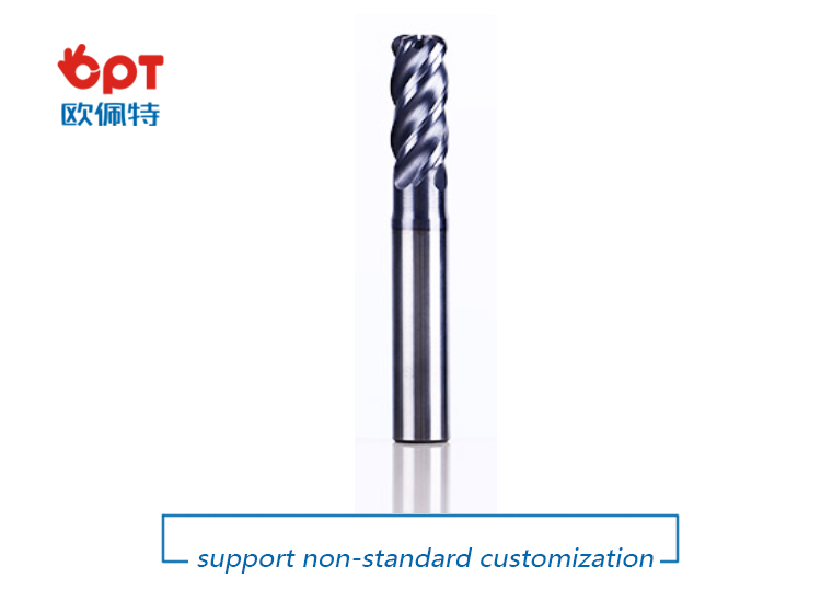
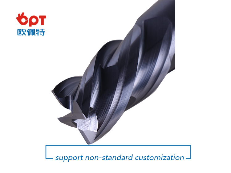
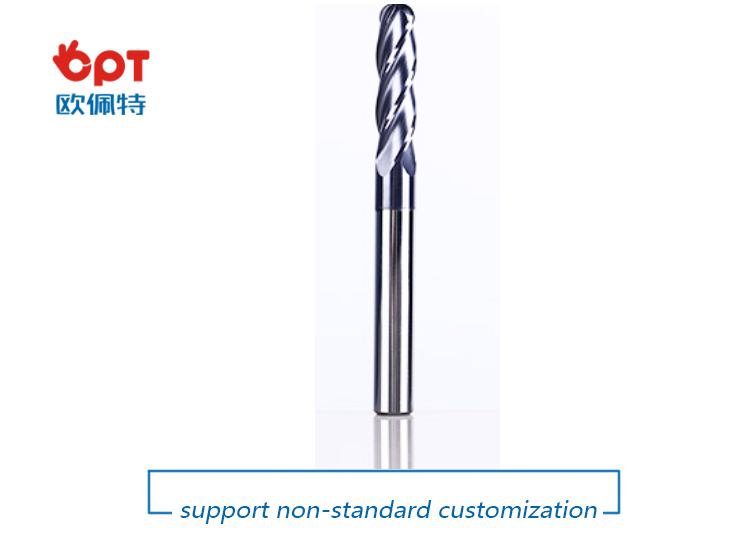
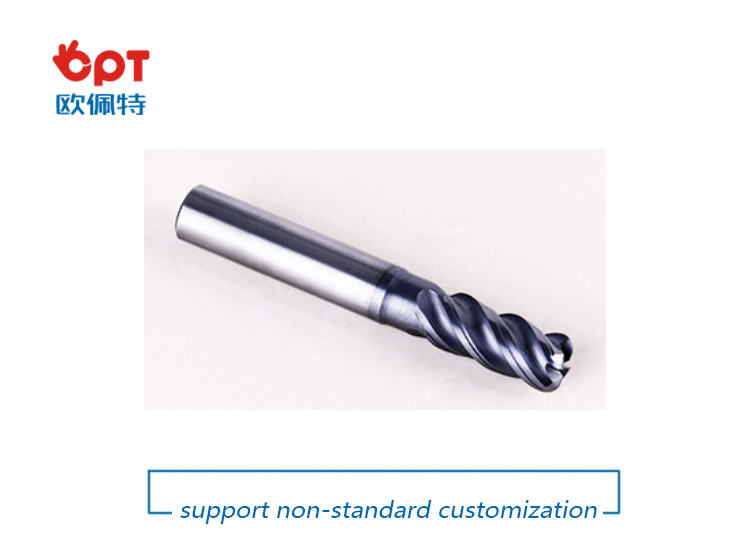
Generally, for applications that require smaller diameters, solid Carbide End Mills are recommended even for roughing and semi-finishing.
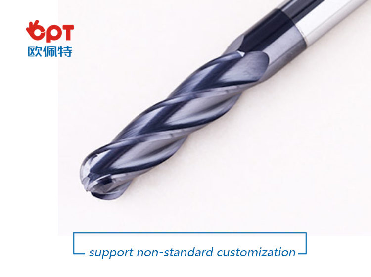
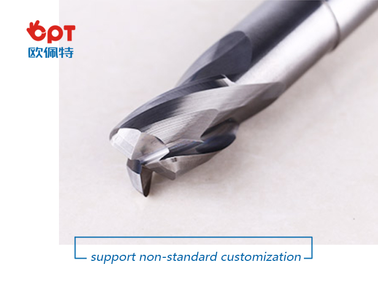
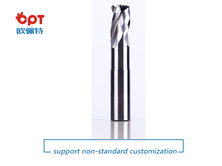
OPT present to our clients a wide variety of solid carbide end mills, these tools are used for cutting cast iron, aluminum, copper, stainless, bronze, heat treated metals and so on. Clients should choose the right solid carbide end mills according to different machined materials, and seclect whether coated or coolant is needed per applications.
Advantage:
Suitable for dynamic milling
One tool for many materials
Cost effective tools
Features
Mills with 1, 2, 3 , 4,or 6 cutting edges
Roughing as well as finishing cutters
A selection of various geometries, comom used type are End mills, Radius end mills, Conical end mills and Roughing end mills etc.
Suitable for regrinding
Flexible in order quantity:
Samples can be provided before mass production, and MOQ can be discussed accordingly.
PRODUCT DETAIL:
PRODUCTING PROGRESS:

PAYMENT AND DELIVERY:

PRODUCT EQUIPMENT :
ABOUT US :
We are specialize in manufacturing PCD diamond tools and Carbide tools. Our major product inclulde PCD Inserts , PCD Reamers , PCD End Mills, PCD Taps, Cabide Inserts,Carbide Drills, Carbide Reams, Taps etc.,
We also offered customized cutting tools per drawings, and provide package according to customer requirements. We manufacture a series range of cutting tools for machining of Cast iron, Aluminium alloy and Non-Ferros metal, it is widely used in all major sectors like Automobiles, Engineering, Aerospace, Aviation and 3C industry. Premium quality of raw material is used in the production and strict examination during processing with advanced equipment, so our client are satisfied with our reliable quality and on-time delivery.
Our best selling of cutting tools include PCD Inserts, PCD End Mill, PCD Ball Nose Mill, PCD Reamer, Carbide Taps , Carbide End Mill, Special Form Cutter and many more. For these years we have been made a large forward in the technologies of manufacturing cutting tools. With high quality on performance and price, our product sells well both on domestic and overseas market. And we will always focus on the quality and best service, to make long business relationship.

quanlity control:
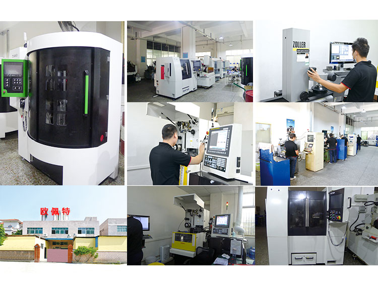
We have dedicated team of quality control and precise equipment to keep good and stable performance for our products and processing services.

Solid Carbide End Mills,End Mill Bits,Carbide End Mill Bits,Solid Carbide Ball End Mill
OPT Cutting Tools Co., Ltd. , https://www.optdiamondtoolss.com