The emergence of portable ECG devices enables ECG signals to be collected in more situations. It can be both movable and can analyze ECG signals in real time. Through the built-in large-capacity storage device, the patient can be monitored for a long time in real time, and the patient's ECG data is recorded, and the data is transmitted to the PC through the USB interface for submission to a professional medical institution for further analysis and diagnosis.
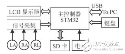
1. Overview of the overall design of the systemThe system block diagram can be represented by Figure 1. The ECG signal is obtained by the electrode and sent to the ECG acquisition circuit. After preamplification, main amplification, high-low-pass filtering, and level raising, the ECG signal that meets the requirements is obtained and sent to the STM32 ADC for AD conversion. In order to better suppress the interference signal, a right leg drive circuit is also introduced in the circuit. The system control chip adopts STM32, TFT-LCD touch function and a small number of buttons to establish a good human-computer interaction environment. It can be displayed and played back in real time through LCD. SD card can store 24h ECG data, and data can be reliably transmitted through USB. Go to the PC to further analyze the ECG data.

Figure 1 Schematic diagram of electrocardiograph
2, the main hardware structure and circuit of the systemThe system is mainly divided into three parts: ECG acquisition circuit, which mainly completes the extraction of ECG signals; bandpass filtering and main amplification circuit, which is used to condition the collected signals to meet the processing requirements; STM32 processing circuit, complete ECG Signal display, analysis, storage and data transfer functions.
2.1, ECG acquisition circuitThe ECG acquisition circuit is the core of the entire portable electrocardiograph, which directly determines the performance of the entire system. The ECG acquisition circuit mainly includes: input buffer and preamplifier, right leg drive, high and low pass filter, main amplification and level up.
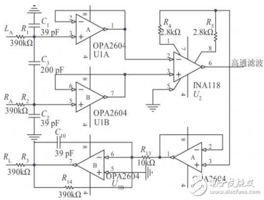
The frequency of the surface ECG signal is mainly concentrated at 0.05-100 Hz, the amplitude is 10μV ~ 4mV, and the typical value is 1mV, which is a low-frequency weak bipolar signal. The STM32's ADC input voltage range is 0 ~ 3.3V, so the ECG signal needs to be amplified and level raised, the overall magnification is about 1000 times, and then raised by about 1V through the level up circuit. In ECG measurement, the actual electrode may not be completely symmetrical, which will cause baseline drift, and there are ubiquitous power line interference (50Hz), myoelectric interference, etc., which require the ECG preamplifier to have Very high common mode rejection ratio. The common mode rejection ratio is generally required to be above 80 dB. The ECG preamplifier circuit and the right leg drive circuit are shown in Figure 2. (The positive and negative power supply of the amplifier is not shown)

Figure 2 ECG preamplifier circuit and right leg drive circuit
This design uses INA118 instrumentation amplifier as the system preamplifier, which has the characteristics of low noise, low drift, high common mode rejection ratio, high input impedance, etc. Its gain can reach 1000 times, and the calculation formula is G=1+50k/Rg. . The electrode polarization voltage can be up to 300mV. In order to prevent the preamplifier from entering the cut-off or saturation state, the amplification factor must be limited. The gain is 10, and G = 1+50/Rg gives Rg=5.6kΨ, and the external resistor Rg is selected. Precision wirewound resistor with a resistance of 5.6kΨ. Since the impedance of the human body and the impedance of the electrocardiogram electrode are very large, a first-order follow-up is designed as a signal buffer before preamplification. In order to better suppress 50Hz interference, the right leg electrode is connected to the amplifier ground via a resistor to reduce the common mode voltage of the human body.
Lamp Holder,Bulb Holder,Light Holder,Lamp Socket
WENZHOU TENGCAI ELECTRIC CO.,LTD , https://www.tengcaielectric.com