Some applications require loose output regulation and less than 20mA. For such applications, linear regulators built with discrete components are a cost-effective solution (Figure 1). For applications with tight output regulation and requiring more current, a high performance low dropout linear regulator (LDO) can be used.
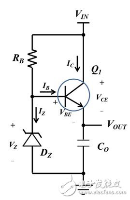
Figure 1: A simple series regulator.
There are two design challenges associated with the circuit shown in Figure 1. The first challenge is to regulate the output voltage. The second challenge is to be safe in the event of a short circuit. In this article, I will discuss how to design robust linear regulators with discrete components.
Below is an example of powering a microcontroller:
· Input range: 8.4V to 12.6V.
· Output range: 1.71V to 3.7V.
• Maximum load current: Io_max = 20mA.
Bipolar NPN transistor selection
The NPN bipolar transistor Q1 is the most important component. I first chose this device. The transistor should meet the following requirements:
• The collector to emitter and base to emitter breakdown voltages should exceed the maximum input voltage Vin_max.
• The maximum allowable current of the collector should exceed the maximum load current Io_max.
In addition to these two basic requirements, it is also a good idea to use components with alternative packages. This flexibility will simplify the design process when it comes to power consumption. I chose an NPN transistor with an alternative package and different power ratings for this application.
The following are the key features of the NPN transistor used by the author.
When IC = 50mA:
Direct current (DC) current gain hFE = 60;
Collector-emitter maximum saturation voltage VCEsat = 300mV;
Base-emitter maximum saturation voltage VBEsat = 950mV.
Zener diode Dz selection
The output voltage is equal to the reverse Zener voltage VZ minus the transistor base to emitter voltage VBE. Therefore, the minimum reverse Zener voltage should meet the following requirements (Equation 1):
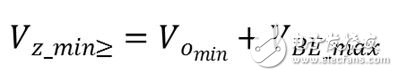
(1)
For this application, one test condition I chose was IZT = 1mA, and I chose a Zener diode with the following characteristics:
When Vo_min = 1.71V and VBE_max = 0.95V, Vz_min should be greater than 2.65V.
When the reverse current IZT = 1 mA, the lowest reverse voltage VZ_min = 2.7V.
When the reverse current IZT = 5mA, the highest reverse voltage VZ_max = 3.8V.
Base pull-up resistor RB
Resistor RB provides current to the Zener diode and the base of the transistor. It should supply enough current under operating conditions. The Zener diode reverse current IZ should be greater than 1 mA, as I discussed in the "Selection of Zener Diode Dz" section. Equation 2 estimates the maximum base current required for operation:
(2)
Where Hfe_min = 60. Therefore, IB_max ≈ 0.333mA.
Equation 3 calculates the value of RB. I used a resistor with 1% tolerance.
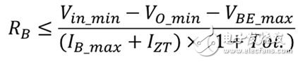
(3)
Therefore, RB should be less than 4.26kΩ. I used a resistor with a standard value of 4.22kΩ.
Add a dummy load resistor for output regulation
When the load current is zero, the output voltage reaches its maximum value. When 1 mA ≤ IZT ≤ 5 mA, the maximum value of VZ is 3.8. VBE(on) should be greater than 0.1V so that the output of the regulator will meet the requirements. In addition, I have added a dummy load resistor to draw the collector current under no load conditions.
Figure 2 shows that VBE(on) can be used as a function of collector current IC. When IC = 0.1mA, VBE(on) is greater than 0.3V.
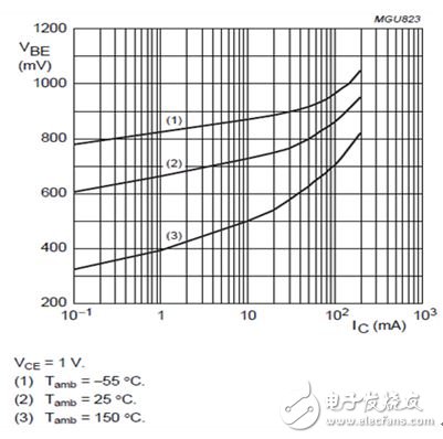
Figure 2: Base-emitter turn-on voltage and collector current
Equation 4 calculates the virtual resistance:
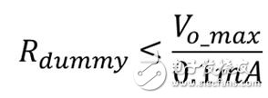
(4)
I added a 36kΩ resistor to the circuit, as shown in Figure 3.
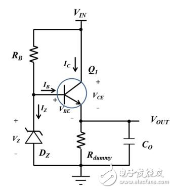
Figure 3: Series Regulator with Virtual Load Resistor
Current limit for short circuit events
The short circuit of the output of the circuit shown in Figure 3 to ground will produce a large collector current. A PSPICE simulation shows that the collector current can be as high as 190mA, see Figure 4.
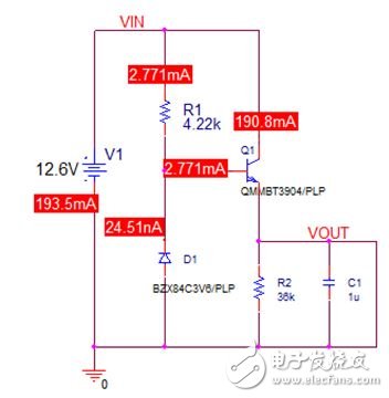
Figure 4: Short circuit simulation results
The power consumption of transistor Q1 is 2.4W. There is no package that can handle this power consumption.
To limit the short circuit current, I added a resistor RC (from VIN to the collector of transistor Q1), as shown in Figure 5.
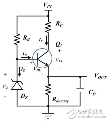
Figure 5: Series Regulator with Current Limiting Resistor
The resistor RC will meet the output regulation requirements and dissipate power during a short circuit event. The author can calculate the value of RC:
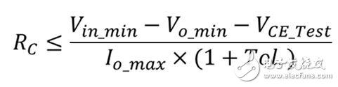
(5)
VCE_Test is the collector-emitter voltage used in Figure 1. The author chose a 5% tolerance resistor for the RC. With Equation 5, the RC should be less than 271 Ω. Using this estimate, Equation 6 calculates the worst-case RC power consumption in a short-circuit event:
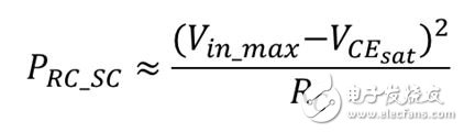
(6)
This power consumption is about 0.56W. I chose a 1W, 270Ω power resistor. For applications with higher RC short-circuit power consumption, you can connect multiple resistors in series to share power consumption.
Component stress analysis
As far as the resistor RC is concerned, the worst case power consumption occurs in the short circuit event with the largest input. Using Equation 6, the maximum power consumption can be calculated to be 0.59W.
As far as the transistor Q1 is concerned, because of the finite current resistor RC, the worst case power consumption does not occur in the short circuit event. The power dissipation of Q1 during normal operation is a function of the collector current, as shown in Equation 7:
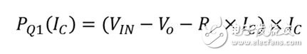
(7)
The worst case occurs when the following conditions are met:
VIN = VIN_max
VO = VO_min
IC = (VIN_max – VO_min)/(2&TImes;RC)
Therefore, the maximum power consumption of Q1 is (VIN_max – VO_min) 2/(4&TImes; RC). In this example it is 110mW. I chose a small outline transistor with a power rating of 350mW and a SOT23 package.
As for the maximum power consumption of the RB, the worst case occurs in the short circuit event with the largest input. The voltage across RB is equal to the input voltage minus VBE(sat). The maximum power consumption is estimated to be 38mW.
In this article, the author describes the design guidelines for robust low-cost linear regulators with discrete components.
Rogowski Coil And Integrator,Rogowski Coil,Integrator For Rogowski Coil,Single Phase Aluminum Alloy Housing Integrator
Zibo Tongyue Electronics Co., Ltd , https://www.tongyueelectron.com