For the resistor, I think everyone thinks it is simple, there is nothing to say. In fact, the resistance should be very extensive, and its role is completely different in different applications. I will summarize the basic usage and the areas that are easily overlooked.
1, concept
Resistivity (usually denoted by "R"), in physics, indicates the magnitude of the conductor's resistance to current. The greater the resistance of the conductor, the greater the resistance of the conductor to the current. Different conductors have different resistances, and resistance is a characteristic of the conductor itself. The resistance will cause a change in the amount of electron flow. The smaller the resistance, the larger the electron flux and vice versa. Superconductors have no resistance.
The resistance value of the resistance element is generally related to temperature, material, length, and cross-sectional area. The physical quantity that measures the magnitude of the resistance of the resistance is the temperature coefficient, which is defined as the percentage change of the resistance value for every 1 °C increase in temperature.
The main physical characteristic of a resistor is that it converts electrical energy into thermal energy. It can also be said that it is an energy-consuming component through which current generates internal energy. The resistor usually functions as a partial pressure or a shunt in the circuit. For signals, both AC and DC signals can pass through the resistor.
The resistance of the conductor is usually indicated by the letter R. The unit of resistance is ohm, referred to as Europe, the symbol is Ω (Greek, read as Omega), 1 Ω = 1V/A. Larger units have kilo ohms (kΩ) and megohms (MΩ) (mega = millions, or 1 million).
KΩ (thousand ohms), MΩ (megohms), their conversion relationship is:
1TΩ=1000GΩ; 1GΩ=1000MΩ; 1MΩ=1000KΩ; 1KΩ=1000Ω (that is, one thousand input rate)
Two resistors in parallel can also be expressed as
Series: R=R1+R2+. . . +Rn
Parallel: 1/R=1/R1+1/R2+. . . +1/Rn Two resistors in parallel can also be expressed as R=R1·R2/(R1+R2)
Definition formula: R=U/I
Decisive formula: R = ÏL / S (Ï represents the resistivity of the resistor, which is determined by its own properties, L represents the length of the resistor, and S represents the cross-sectional area of ​​the resistor)
The resistance value of a resistive element is generally related to temperature and to the length of the conductor, the cross-sectional area, and the material. The physical quantity that measures the magnitude of the resistance affected by temperature is the temperature coefficient, which is defined as the percentage change in resistance value for every 1 °C increase in temperature. Most (metal) resistance increases with increasing temperature, and some semiconductors do the opposite. Such as: glass, carbon in the case of a certain temperature, there is a formula R = Ïl / s where Ï is the resistivity, l is the length of the material, the unit is m, s is the area, the unit is square meters. It can be seen that the resistance of the material is proportional to the length of the material and inversely proportional to its area.
The physical quantity of the resistor: 1 ohm voltage produces a ohm current and 1 ohm resistor. In addition to the function of the resistor used in the circuit to control the current and voltage, it can also be used as a heating element.
2, resistance application
The main role of the resistor in the circuit is shunt, current limit, voltage divider, bias, filtering (combined with capacitors) and impedance matching.
Resistance is usually divided into three categories: fixed resistors, variable resistors, and special resistors.
In electronic products, it is most commonly applied with fixed resistors. Commonly used and commonly used are RT type carbon film resistors, RJ type metal film resistors,
RX type wirewound resistors, chip resistors widely used in recent years.
Resistor model name: R for resistance, T-carbon film, J-metal, X-wire winding, is the first letter of Pinyin. In domestically produced old-fashioned electronic products, it is often seen that the resistance of the exterior is coated with green paint, that is, the RT type. The red color resistor is RJ type.
According to the power, it can be divided into small power resistors and high power resistors. The high-power resistor is usually a metal resistor. In fact, it should be a metal (aluminum) heat sink outside the metal, so it can have more than 10W; it can be easily seen on the market in the electronics market. .
Metal resistors are typically used as loads or as outdoor heaters for small devices, as can be seen in some decoder boxes and all weather guards in CCTV.
The resistor acts as a current limiting and voltage dividing in the circuit. Usually 1/8W resistors are fully satisfactory. However, in the case of a 7-segment LED, the difference between the voltage drop of the LED and the supply voltage should be taken into consideration, and then the maximum current of the LED is considered, usually 20 mA (ultra-high brightness LED), if it is 2×6 (2 rows of 6 In series), the current is 40mA.
Different manufacturers choose different materials, and the pressure drop is also different. So you need to add electricity to measure it. However, do not let the current of a single LED exceed 20mA. At this time, the current will not increase in brightness, but the life of the LED will decrease. The size of the current limiting resistor is the voltage drop divided by the current. The power of the resistor can be calculated.
Potentiometer
The potentiometer is an adjustable resistor. Its resistance varies from 1 to nΩ. For example, N=102=10×10 is the power of 2, which is 1000 ohm, 1KΩ. Similarly, 502 = 5KΩ.
The potentiometer is divided into single-turn and multi-turn potentiometers. The single-turn potentiometer is usually gray-white with a cross-adjustable knob on the surface. It is placed in a fixed position before the factory, not at the 2 heads; the multi-turn potentiometer is usually blue, and the adjusted knob is a word. One-word small screwdriver is adjustable; multi-turn potentiometer is divided into two types: top adjustment and side adjustment, which is mainly convenient for debugging the circuit board.
Some are instrumentation equipment, usually analog circuits, there are some uncertain factors that need to be adjusted to achieve the best results; some are devices that need to output a variable thing, such as voltage and current, also need a potentiometer .
Row resistance
Is the sip n package, the more commonly used is the resistance of the 502 and 103 9-pin resistor row; like sip9 is 8 resistors packaged together, 8 resistors have one end connected together, is the common end, used in the row resistance A small white dot indicates. The row resistance is usually black and yellow; 51 system P0 needs a row resistor pull-up; otherwise, when it is input, the data cannot be read normally; when it is output, 7407 is OK, no pull-up resistor is needed; However, it is still not possible to pick up other chips. Interested can look at the structure of 51 P0; no interest, according to the gourd painting, it is correct.
Photoresistance
When the intensity of light incident on the photoresistor changes, the resistance value also changes. Obviously this is a property of semiconductor materials.
The change in light intensity can be detected using a photoresistor.
Resistor package
The resistor package is available in a surface mount and an axial package. The axial package is: axial0.4, axial0.6, axial0.8, etc.; axial is the meaning of the axis in English; the most commonly used surface mount resistor is 0805; of course, there is a larger; but larger Resistance is not very common.
3, current limiting resistor
Resistor as a current limit should be one of the most commonly used applications. For the peripheral design of a microcontroller, the application of the resistor is very important. In many cases, we must connect a current limiting resistor to the I/O port of the microcontroller to ensure that the peripheral circuit does not. Will use short circuit, overload and other reasons to burn out the I / O port of the microcontroller, or even the entire microcontroller.
For the current limit, everyone must be very clear, but what is your standard when choosing the resistance value? Do you know that the microcontroller port is the maximum input current? Do you know the maximum output current of the microcontroller? Do you know the maximum voltage that the microcontroller port can withstand?
Faced with these problems, I am afraid that many people are aware of the fact that they do not know why, and they rely on experience to obtain them. They do not fully calculate the value according to the requirements of the circuit. To this end, I ask these questions here, I don't want to teach you how to calculate these values. Anyone who knows Ohm's law should know how to calculate it. So, I just hope that everyone can understand these parameters of the MCU before choosing. Then, Calculated according to the parameters. Be sure to leave some reserved space when calculating.
IOL, what exactly does IOH mean?
When looking at the DATASHEET files of some components, I often encounter the parameters of the components, IOL, IOH, IIL, IIH. I also know that they refer to the maximum and minimum currents when the input and output are high and low, but when they are connected, they The matching problem has been very vague, such as: IOL=1.5MA; IOH=-300UA
The other input is:
IIL=-100UA; IIH=10UA;
Can they directly connect with each other? IOL, IOH, what exactly is it referring to? Is it a driver?
Reference answer:
IIL and IIH indicate the current value when the input is high and low, and the - sign indicates the current flowing from the device.
IOL and IOH indicate the current value when the output is low and high, and the same - sign indicates the current flowing from the device.
The first device you said means that it can sink (flow) 1.5mA when the output is low, and 300uA when the output is high. The second device indicates that 100uA will flow out when the input is low and 10uA when the input is high. |IOL|> |IIL|,|IOH|> |IIH| means that the output device can drive the input device.
4, pull-down resistor
Another application of the resistor is the pull-up resistor. Pull-up is to clamp the indeterminate signal through a resistor to the high level, and the resistor acts as a current limiter. Pull down the same reason. It is also the ability to clamp an indeterminate signal through a resistor at a low level.
Pull-up is the input current to the device, pull-down is the output current; the strength is only the resistance of the pull-up resistor is different, there is no strict distinction; for the non-collector (or drain) open-circuit output type circuit (such as ordinary gate circuit) to boost the current The ability of the voltage and the voltage is limited. The function of the pull-up resistor is mainly to output the current channel for the open-collector output type circuit.
*1 When the TTL circuit drives the CMOS circuit, if the high level of the circuit output is lower than the lowest level of the CMOS circuit (typically 3.5V), then the pull-up resistor needs to be connected to the output of the TTL to improve the output. The value of the high level.
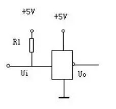
*2 The OC gate must use a pull-up resistor to increase the high value of the output.
*3 To enhance the drive capability of the output pins, pull-up resistors are often used on some microcontroller pins.
*4 On the CMOS chip, in order to prevent damage caused by static electricity, unused pins cannot be left floating. Generally, pull-up resistors are connected to reduce the input impedance and provide a discharge path.
*5 The pin of the chip is added with a pull-up resistor to increase the output level, thereby improving the noise margin of the chip input signal and enhancing the anti-interference ability.
*6 Improve the anti-electromagnetic interference capability of the bus. It is easier to accept external electromagnetic interference when the pin is left floating.
*7 Resistor mismatch in long-line transmission is likely to cause reflected wave interference. Plus, pull-down resistor is resistance matching, which effectively suppresses reflected wave interference.
Pull-up resistor
Is the resistor from the high level of the power supply to the output
*1 If the level is output with OC (Open Collector, TTL) or OD (Open-Drain, CMOS), then the pull-up resistor does not work. It is easy to understand that the tube cannot output a high level without a power supply. .
*2 If the output current is large, the output level will decrease (there is already a pull-up resistor in the circuit, but the resistance is too large, the voltage drop is too high), and the pull-up resistor can be used to provide the current component. "Pull high." (There is a resistor on the pull-up resistor inside the IC, when the total resistance is reduced and the total current is increased). Of course, the pull-up resistor of the tube operating in the linear range as needed should not be too small. Of course, this method is also used to achieve the matching of the gate circuit levels.
Why use pull-up resistors?
Generally, when the single button is used for triggering, if the IC itself does not have an internal resistor, in order to maintain the single button in the untriggered state or return to the original state after the trigger, another resistor must be connected outside the IC.
Digital circuits have three states: high, low, and high-impedance. Some applications do not expect a high-impedance state. They can be stabilized by pull-up or pull-down resistors, depending on design requirements. !
Generally speaking, I/O ports, some can be set, some can not be set, some are built-in, some need to be external, the output of I/O port is similar to C of a triode, when C is connected through a resistor and power supply Together, the resistor becomes a pull-up resistor, that is, the port is high when it is normal; when C is connected to ground through a resistor, the resistor is called a pull-down resistor.
Pull-up resistors are used to solve the problem of providing current when the bus drive capability is insufficient. The general statement is that the pull-up increases the current, and the pull-down resistor is used to sink the current.
5, typical application
*1 fixed level
When the peripheral does not receive control, we need to fix a peripheral or microcontroller I / O port at a fixed level, you need to connect the pull-down resistor as needed, for example:
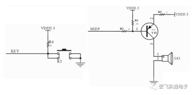
In the above figure, for the key input, if there is no pull-up resistor, if there is no pull-up resistor, the MCU port will be in a suspended state, there is no certain level, except for the MCU with internal pull-up resistor, plus The pull-up resistor will, when there is no button, the MCU port will remain high. When there is a button, the MCU port will input a low level. For the buzzer, since it has the same effect as the button, without the pull-up resistor, it is impossible to distinguish the working state of the triode when there is no single-chip control. Therefore, a pull-up resistor must be added to ensure that there is no single-chip control. The triode is turned off and the buzzer does not work.
*2 level input
Sometimes due to the design of the device itself, if the external pull-down resistor is not connected, the device cannot normally achieve high and low level conversion. For example, for an open-drain output I2C bus, if the pull-up resistor is not connected, it can only output a low level, and cannot achieve a high-level output. Plus a pull-up resistor ensures that when there is no control signal, it is pulled up. The resistor achieves a high level.
The second circuit design of the single chip: capacitor
Capacitors, as another basic component of electronic circuits, are familiar to everyone. Let's talk about some basic applications and considerations of capacitors. However, due to the wide application of capacitors, it may not be all-inclusive. If there is a place that netizens feel that they have not talked about, they hope that the public will be perfect.
1, concept
Capacitance, also known as "capacity", refers to the amount of charge stored at a given potential difference, denoted as C, and the international unit is Farad (F). Generally, the electric charge moves in the electric field. When there is a medium between the conductors, the electric charge is hindered and the electric charge accumulates on the conductor, causing the accumulated storage of the electric charge. The stored electric charge amount is called a capacitance. Capacitance is one of the most widely used electronic components in electronic devices. It is widely used in blocking, coupling, bypassing, filtering, tuning loops, energy conversion, and control circuits.
Capacitance (or capacitance) is the physical quantity that represents the charge capacity of a capacitor.
Capacitively, it is a static charge storage medium. It may be a permanent charge. This is its characteristic. It is widely used. It is an indispensable electronic component in the field of electronics and power. Mainly used in power supply filtering, signal filtering, signal coupling, resonance, filtering, compensation, charge and discharge, energy storage, DC blocking and other circuits.
In circuit science, given the potential difference, the capacitor's ability to store charge, called capacitance, is labeled C. In the International System of Units, the unit of capacitance is farad, labeled F.
The sign of the capacitor is C.
C=εS/d=εS/4πkd (vacuum)=Q/U
In the International System of Units, the unit of capacitance is Farah, referred to as the law,
The symbol is F. Since the unit of Farah is too large, the commonly used capacitance units are millifarad (mF), microfarad (μF), nanofarad (nF), and picofarad (pF). The conversion relationship is:
1 Farad (F) = 1000 millifarads (mF) = 1000000 microfarads (μF)
1 microfarad (μF) = 1000 nanofarads (nF) = 1,000,000 picofarads (pF).
The relationship between capacitance and battery capacity:
1 volt ampere = 1 watt hour = 3600 joules
w=0.5cuu
A capacitor, if the potential difference between the two stages is 1 volt, the capacitance of this capacitor is 1 method, namely: C = Q / U but the size of the capacitor is not by Q (charge) or U (voltage) Determined, namely: C = εS / 4πkd. Where ε is a constant, S is the facing area of ​​the capacitor plate, d is the distance of the capacitor plate, and k is the electrostatic force constant. A common parallel plate capacitor has a capacitance of C = εS / d (ε is the dielectric constant of the dielectric between the plates, S is the plate area, and d is the distance between the plates).
Definition: C=Q/U
The formula for calculating the potential energy of a capacitor: E=CU^2/2=QU/2=Q^2/2C
Multi-capacitor parallel calculation formula: C=C1+C2+C3+...+Cn
Multi-capacitor series calculation formula: 1/C=1/C1+1/C2+...+1/Cn
Three capacitors in series: C=(C1*C2*C3)/(C1*C2+C2*C3+C1*C3)
Capacitance refers to the ability to accommodate an electric field. Any electrostatic field is composed of many capacitors. There are capacitors in the electrostatic field. Capacitors are described by electrostatic fields. It is generally believed that the isolated conductor forms a capacitance with the infinity, and the conductor ground is equivalent to being connected to infinity and connected to the earth as a whole.
2, the application of capacitors
Capacitors exhibit different states depending on the location of the capacitor in the circuit. The common classifications are as follows:
*1 According to the structure, there are three categories: fixed capacitors, variable capacitors and trimmer capacitors;
*2 According to electrolyte classification: organic dielectric capacitors, inorganic dielectric capacitors, electrolytic capacitors and air dielectric capacitors;
*3 According to usage: high frequency bypass, low frequency bypass, filtering, tuning, high frequency coupling, low frequency coupling, small capacitor;
*4 frequency bypass: ceramic capacitors, mica capacitors, glass film capacitors, polyester capacitors, glass glaze capacitors;
*5 Low frequency bypass: paper capacitor, ceramic capacitor, aluminum electrolytic capacitor, polyester capacitor;
*6 Filtering: aluminum electrolytic capacitors, paper capacitors, composite paper capacitors, liquid tantalum capacitors;
*7 Tuning: ceramic capacitors, mica capacitors, glass film capacitors, polystyrene capacitors;
*8 High frequency coupling: ceramic capacitors, mica capacitors, polystyrene capacitors;
*9 Low coupling: paper capacitors, ceramic capacitors, aluminum electrolytic capacitors, polyester capacitors, solid tantalum capacitors;
*10 Small capacitors: metallized paper capacitors, ceramic capacitors, aluminum electrolytic capacitors, polystyrene capacitors, solid tantalum capacitors, glass glaze capacitors, metalized polyester capacitors, polypropylene capacitors, mica capacitors.
Capacitance
* The basic function of capacitors is charging and discharging, but many circuit phenomena extended by this basic charging and discharging effect make capacitors have various uses, such as: in electric motors, use it to produce phase shift; In the flash, use it to generate high-energy instant discharges and so on. In electronic circuits, the use of different properties of capacitors is particularly high. Although many different uses, there are also very different uses, but their functions are all from charging and discharging.
Below is a list of the roles of some capacitors:
Coupling Capacitor: The capacitor used in the coupling circuit is called a coupling capacitor. This type of capacitor circuit is widely used in RC-coupled amplifiers and other capacitive coupling circuits to isolate DC-DC.
Filter Capacitor: A capacitor used in a filter circuit is called a filter capacitor. This capacitor circuit is used in power supply filtering and various filter circuits. The filter capacitor removes signals in a certain frequency band from the total signal.
Decoupling Capacitors: Capacitors used in decoupling circuits are called decoupling capacitors. This type of capacitor circuit is used in the DC voltage supply circuit of a multistage amplifier. The decoupling capacitor eliminates unwanted low frequency crosstalk between each stage of the amplifier.
High-frequency vibration-absorbing capacitor: The capacitor used in the high-frequency vibration-damping circuit is called the high-frequency vibration-absorbing capacitor. In the audio negative feedback amplifier, in order to eliminate the high-frequency self-excitation that may occur, this capacitor circuit is used to eliminate The high frequency howling that the amplifier may appear.
Resonant Capacitor: Capacitors used in LC resonant circuits are called resonant capacitors, and such capacitor circuits are required in both LC parallel and series resonant circuits.
Bypass capacitor: The capacitor used in the bypass circuit is called bypass capacitor. If the signal in a certain frequency band needs to be removed from the signal in the circuit, the bypass capacitor circuit can be used. According to the frequency of the removed signal, there is a full frequency domain. (All AC signals) Bypass capacitor circuit and high frequency bypass capacitor circuit.
Neutralization Capacitor: The capacitor used in the neutralization circuit is called the neutralization capacitor. In radio high frequency and intermediate frequency amplifiers, TV high frequency amplifiers, this neutralization capacitor circuit is used to eliminate self-excitation.
Timing Capacitor: A capacitor used in a timing circuit is called a timing capacitor. A timing capacitor circuit is used in a circuit that requires time control by capacitor charging and discharging, and the capacitor controls the magnitude of the time constant.
Integral Capacitor: A capacitor used in an integrating circuit is called an integrating capacitor. In the synchronous separation circuit for scanning the potential field, the field synchronization signal can be taken out from the field composite synchronization signal by using the integrating capacitance circuit.
Differential Capacitor: A capacitor used in a differential circuit is called a differential capacitor. In order to obtain the apex trigger signal in the flip-flop circuit, the differential capacitance circuit is used to obtain a cusp pulse trigger signal from various types of (mainly rectangular pulse) signals.
Compensation capacitor: The capacitor used in the compensation circuit is called the compensation capacitor. In the bass compensation circuit of the deck, this low-frequency compensation capacitor circuit is used to boost the low-frequency signal in the playback signal. In addition, there is a high-frequency compensation capacitor. Circuit.
Bootstrap Capacitor: The capacitor used in the bootstrap circuit is called the bootstrap capacitor. The commonly used OTL power amplifier output stage circuit uses this bootstrap capacitor circuit to boost the positive half-cycle amplitude of the signal by positive feedback.
Dividing capacitor: The capacitor in the frequency dividing circuit is called the frequency dividing capacitor. In the speaker frequency dividing circuit of the speaker, the frequency dividing capacitor circuit is used to make the high frequency speaker work in the high frequency band, and the intermediate frequency speaker works in the middle frequency band, the low frequency. The speaker works in the low frequency range.
Load capacitance: refers to the effective external capacitance that determines the resonant frequency of the load together with the quartz crystal resonator. Standard values ​​commonly used for load capacitors are 16pF, 20pF, 30pF, 50pF, and 100pF. The load capacitance can be adjusted according to the specific situation. The adjustment can generally adjust the operating frequency of the resonator to the nominal value.
Tuning Capacitor: Connected to both ends of the oscillating coil of the resonant circuit to play the role of selecting the oscillating frequency.
Pad Capacitor: An auxiliary capacitor in series with the main capacitor of the resonant circuit. Adjusting it can make the frequency range of the oscillating signal smaller and significantly increase the oscillating frequency at the low frequency end.
The neutralization capacitor is connected between the base and the emitter of the triode amplifier to form a negative feedback network to suppress self-oscillation caused by the inter-electrode capacitance of the triode.
Stabilized capacitor: In the oscillating circuit, it acts as a stable oscillating frequency.
Timing capacitor: In the RC time constant circuit, it is connected in series with the resistor R to determine the capacitance of the charging and discharging time.
Acceleration capacitor: Connected to the oscillator feedback circuit to accelerate the positive feedback process and increase the amplitude of the oscillating signal.
Capacitance reduction: In UHF tuner circuits, capacitors connected in series to shorten the length of the oscillating inductor.
Clappa Capacitor: In a three-point capacitor oscillating circuit, a capacitor in series with an inductive oscillating coil acts to eliminate the effect of transistor junction capacitance on frequency stability.
Sira capacitor: In the capacitor three-point oscillating circuit, the capacitor connected in parallel with the two ends of the inductor oscillating coil acts to eliminate the junction capacitance of the transistor, making the oscillator easy to start at the high frequency end.
Stabilizing capacitor: In the discriminator, used to stabilize the amplitude of the output signal.
Pre-emphasis capacitor: In order to avoid the attenuation and loss of the frequency division of the audio modulation signal during processing, the RC high-frequency component is set to increase the network capacitance.
De-emphasis capacitor: In order to restore the original audio signal, it is required to attenuate the high-frequency component and noise boosted by the pre-emphasis in the audio signal, and set the capacitance of the RC in the network.
Phase shift capacitor: A capacitor used to change the phase of an AC signal.
Feedback Capacitor: A capacitor that is connected across the input and output of the amplifier to return the output signal to the input.
Bucking current limiting capacitor: connected in series in the AC loop, using the capacitive reactance characteristics of the capacitor to limit the AC current, thus forming a voltage dividing circuit.
Reverse-pass capacitor: used in the line scan output circuit, and connected between the collector and emitter of the line output tube to generate high-voltage line scan sawtooth wave reverse pulse, the withstand voltage is generally above 1500 volts.
S correction capacitor: connected in series in the deflection coil loop to correct the extended linear distortion of the edge of the tube.
Bootstrap boost capacitor: Use the charge and discharge energy storage characteristics of the capacitor to raise the potential of the circuit at a certain point, so that the potential at this point reaches twice the voltage value of the power supply terminal.
Elimination point capacitor: Set in the view-and-discharge circuit to remove the residual bright spot capacitance on the picture tube when shutting down.
Soft-start capacitor: It is generally connected to the base of the switching tube of the switching power supply to prevent excessive surge current or excessive peak voltage from being applied to the base of the switching tube when the power is turned on, resulting in damage to the switching tube.
The starting capacitor is connected in series with the secondary winding of the single-phase motor to provide a starting phase-shifted AC voltage for the motor, which is disconnected from the secondary winding after the motor is in normal operation.
Operating Capacitor: Connects in series with the secondary winding of the single-phase motor to provide phase-shifted AC current to the secondary winding of the motor. When the motor is in normal operation, it is connected in series with the secondary winding.
3, decoupling capacitor
Capacitors are used in a wide variety of applications, the most common of which is decoupling capacitors. This general application is next to the power supply in order to reduce the AC impedance of the power supply to ground (also known as bypass capacitor). In the absence of this capacitor, the AC characteristics of the circuit become very strange, and the circuit oscillates in severe cases. To this end, each power supply input pin of the microcontroller and other peripheral devices should be added with a bypass capacitor.
The impedance of the capacitor is 1/(2Ï€*f*C), and the higher the frequency, the smaller the impedance should be. Structurally, a small-capacity capacitor is at a high frequency, while a large-capacity capacitor is at a lower frequency, and the impedance of the capacitor becomes the lowest. Therefore, it is necessary to connect a small capacitor and a large capacitor in parallel with the power supply to reduce the impedance of the power supply to ground over a wide frequency range.
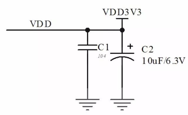
A small-capacity capacitor lowers the impedance at a high frequency, so if it is not disposed near the circuit, the lead of the capacitor grows, and the impedance of the power supply cannot be lowered due to the impedance of the lead itself. When using a small capacitor, it must be as close as possible to the power input pin of the device, otherwise it does not make sense to add this capacitor. Due to its low frequency characteristics, bulk capacitors can be properly spaced from the device during layout without problems. Even if there is no small capacitor C1 on the low frequency circuit, the circuit can work normally. However, in high-frequency circuits, C1 plays a more important role than the large capacitor C2.
Generally, a small-capacity capacitor is a ceramic capacitor of 0.01 to 0.1 uF (film capacitor is NG), and a large-capacity capacitor is an aluminum electrolytic capacitor of 1 to 100 uF. In practical applications, small-capacity capacitors often take 104 capacitors, and large-capacity capacitors often take 10uF capacitors.
Habitually speaking, the bypass capacitor also has two capacitors in size, forming two paths and also ensuring the reliability of the circuit.
The power supply is the basis for the circuit to work. Therefore, the bypass capacitor can be considered as the "insurance" for the operation of the circuit. In the circuit diagram, it is necessary to add a bypass capacitor, so from a person's application of the bypass capacitor, especially the layout can be seen whether it is a master.
4, coupling capacitor
Coupling capacitors, also known as electric field coupling or electrostatic coupling, are a coupling method due to the presence of distributed capacitance. The coupling capacitor is such that the two systems of strong and weak current are coupled and isolated by the capacitor, providing a high-frequency signal path, preventing the power frequency current from entering the weak current system, and ensuring personal safety. In addition to the above functions, the coupling capacitor with voltage extraction device can also extract the power frequency voltage for protection and reclosing to function as a voltage transformer.
The function of capacitive coupling is to pass the AC signal from the previous stage to the next stage. The coupling method is also a direct coupling and a transformer coupling method. The direct coupling efficiency is the highest, and the signal is not distorted. However, the adjustment of the front and rear working points is complicated and involved. In order to make the working point of the latter stage not affected by the previous level, it is necessary to separate the former stage and the latter stage in the DC direction, and at the same time, the AC signal can be smoothly transmitted from the previous stage to the latter stage, and at the same time, The way to accomplish this task is to use capacitive transmission or transformer transmission. They can transmit AC signals and block DC, so that the working points of the front and rear stages are not involved. But the difference is that when transmitting with a capacitor, the phase of the signal is delayed. When transmitting with a transformer, the high-frequency component of the signal is lost. Under normal circumstances, when a small signal is transmitted, a commonly used capacitor is used as a coupling element. When a large signal or a strong signal is transmitted, a common transformer is used as a coupling element.
The coupling capacitor takes advantage of one of the most important characteristics of the capacitor: direct crossover. Through this feature, the DC circuit and the AC circuit can be well coupled to ensure mutual coordination. For the peripheral circuits of the microcontroller, the more coupling capacitors used are where the microcontroller needs to communicate with the AC signal, such as ADC and DAC.
In AD on the DA circuit, we need to convert the digital signal and the analog signal to each other. To ensure that the digital likes and the analog like do not interfere with each other, we often need to connect a capacitor in series with the input or output of the microcontroller to couple the circuit. .
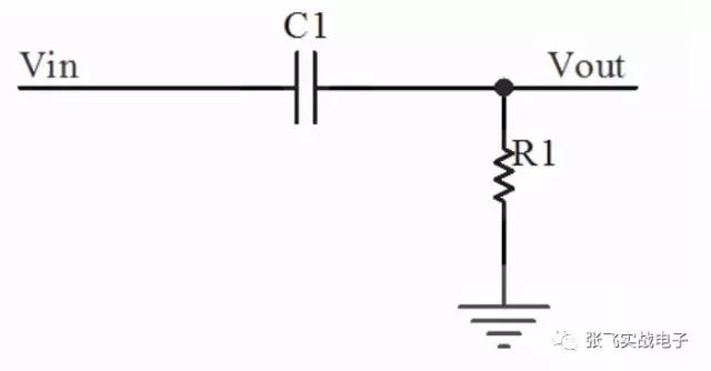
Since the coupling capacitor and the load R1 directly form a high-pass filter, the capacitance should be changed accordingly because the output terminal is connected to the input impedance of different output circuits. For this reason, it is crucial to consider what kind of load to pick up in advance.
5, starting capacitor
A capacitor used in an oscillating circuit that cooperates with an inductor or a resistor to determine the oscillation frequency (time) is called an oscillating capacitor.
Check the data sheet to find out the relationship between the actual frequency and the nominal frequency:
Fx = F0(1+C1/(C0+CL))^(1/2);
And CL = Cg * Cd / (Cg + Cd) + Cs; where Cs is stray capacitance, Cg and Cd are the two external capacitors we add, usually the values ​​are equal, they are connected in series with stray capacitance Is the load capacitance of the crystal CL.
The specific formula does not need to be considered, we can know that the reduction of the load capacitance can make the actual frequency Fx become larger.
We can only change Cg and Cd. Through preliminary calculations, it is found that CL changes by 1pF, and Fx can change several hundred Hz.
The original circuit uses two capacitors of 33pF, which is 16.5pF in parallel. Our chip capacitors are only 27pF, 33pF, 39pF, so we chose 27pF and 39pF in parallel, the capacitance is 15.95pF. After the capacitor was soldered, the measurement was more than 200 Hz larger than the original and fell within the design range.
Conclusion: The two capacitors on the crystal oscillator circuit can be unequal. The value of the trimmer capacitor can be used to fine tune the oscillation frequency of the crystal oscillator. However, if you measure a few crystal oscillators, the frequency is large and small, and the offset is large, then the crystal oscillator is not qualified.
For this capacitor, you should be familiar with it. Basically, no circuit with a microprocessor has at least one circuit with a starting capacitor. Although, most of the time, we are choosing these two capacitors according to experience. In fact, this is not scientific, and sometimes the crystal does not work. Therefore, it is still necessary to choose the appropriate starting capacitor. In fact, different crystal oscillators need different starting capacitors. When purchasing a crystal oscillator, you should choose a suitable crystal oscillator. Generally speaking, the crystal oscillator data sheet also provides the basis for selecting the starting capacitor.
Anyway, in general, we can still have capacitance based on experience:
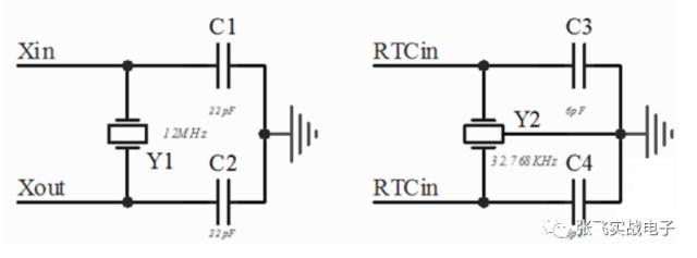
In the main clock input circuit of the single chip microcomputer, it is generally possible to select a starting capacitor of about 22pF, and selecting a starting capacitor of 6pF in the RTC clock is no problem. Of course, if the clock requirements are strict, it is recommended to refer to the crystal data sheet and select the capacitor.
6, reset capacitor
As shown in the figure is a capacitor reset circuit. Al is a CPU integrated circuit, and one pin is a reset pin of the integrated circuit A1. The reset pin is generally represented by RESET. The circuit in the 1-pin circuit and the external circuit constitute a reset circuit, Cl is a reset capacitor, and Sl is a manual reset switch. The working principle of this reset circuit: the inner circuit of the I integrated circuit Al has a Schmitt trigger and a pull-up resistor R1, one end of which is connected to the DC voltage +5V, and the other end is connected to the 1st and the outside of the Al. The capacitor C1 in the circuit is connected.
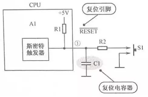
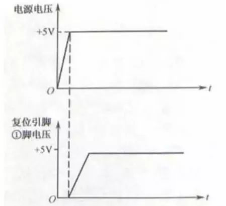
After the power switch of the circuit is turned on, the +5V DC voltage charges the capacitor C1 through the resistor R1, so that there is no voltage across the capacitor C1 when the power is turned on (because the voltage across the capacitor cannot be abruptly changed), as the capacitor C1 is charged, The voltage on pin 1 of the integrated circuit A1 starts to rise, so that a reset pulse of sufficient time can be generated on the 1 pin of Al, and the time constant is generally 0.2 s.
With the charging of +5V DC voltage, the voltage on the 1 pin of Al reaches a certain value, all the circuits inside the integrated circuit A1 can establish the initial state, the reset operation is completed, and the CPU enters the initial normal working state. The purpose of this reset circuit is to make the DC voltage on the reset pin 1 of the integrated circuit A lag behind the specified time of the +5V DC working voltage of the integrated circuit A1, as shown in the voltage waveform shown in Figure 5-69. A problem.
The third circuit design of single chip microcomputer: inductance
As a special device capable of changing current, inductors are relatively rare in digital circuits and are generally used in power-related parts.
1, concept
Inductance of an ideal inductor is an attribute of a closed loop. When the coil passes current, a magnetic field induction is formed in the coil, which in turn generates an induced current to resist current flow through the coil. The interaction between this current and the coil is called the electrical inductive reactance, which is the inductance, and the unit is "Henry (H)".
电感是é—åˆå›žè·¯çš„一ç§å±žæ€§ï¼Œå³å½“通过é—åˆå›žè·¯çš„电æµæ”¹å˜æ—¶ï¼Œä¼šå‡ºçŽ°ç”µåŠ¨åŠ¿æ¥æŠµæŠ—电æµçš„改å˜ã€‚è¿™ç§ç”µæ„Ÿç§°ä¸ºè‡ªæ„Ÿï¼ˆself-inductance),是é—åˆå›žè·¯è‡ªå·±æœ¬èº«çš„属性。å‡è®¾ä¸€ä¸ªé—åˆå›žè·¯çš„电æµæ”¹å˜ï¼Œç”±äºŽæ„Ÿåº”作用而产生电动势于å¦å¤–一个é—åˆå›žè·¯ï¼Œè¿™ç§ç”µæ„Ÿç§°ä¸ºäº’感(mutual inductance)。
自感
当线圈ä¸æœ‰ç”µæµé€šè¿‡æ—¶ï¼Œçº¿åœˆçš„周围就会产生ç£åœºã€‚当线圈ä¸ç”µæµå‘生å˜åŒ–时,其周围的ç£åœºä¹Ÿäº§ç”Ÿç›¸åº”çš„å˜åŒ–,æ¤å˜åŒ–çš„ç£åœºå¯ä½¿çº¿åœˆè‡ªèº«äº§ç”Ÿæ„Ÿåº”电动势(感生电动势)(电动势用以表示有æºå…ƒä»¶ç†æƒ³ç”µæºçš„端电压),这就是自感。
互感
两个电感线圈相互é 近时,一个电感线圈的ç£åœºå˜åŒ–将影å“å¦ä¸€ä¸ªç”µæ„Ÿçº¿åœˆï¼Œè¿™ç§å½±å“就是互感。互感的大å°å–决于电感线圈的自感与两个电感线圈耦åˆçš„程度,利用æ¤åŽŸç†åˆ¶æˆçš„元件å«åšäº’感器。
电感符å·ï¼šL
电感å•ä½ï¼šäº¨ï¼ˆH)ã€æ¯«äº¨ï¼ˆmH)ã€å¾®äº¨ï¼ˆÎ¼H),æ¢ç®—关系为
1H=10^3mH=10^6μH=10^9nH。
æ¢ç®—:数值X10çš„n次方如103 å³ä¸º10X10的三次方nh 为10uh
除æ¤å¤–还有一般电感和精密电感之分
一般电感:误差值为20%,用M表示;误差值为10%,用K表示。
精密电感:误差值为5%,用J表示;误差值为1%,用F表示。
如:100M,å³ä¸º10μH,误差20%。
2ã€ç”µæ„Ÿåº”用
电感是用ç»ç¼˜å¯¼çº¿(例如漆包线,沙包线ç‰)绕制而æˆçš„电ç£æ„Ÿåº”元件。属于常用元件。
电感的作用:通直æµé˜»äº¤æµè¿™æ˜¯ç®€å•çš„说法,对交æµä¿¡å·è¿›è¡Œéš”离,滤波或与电容器,电阻器ç‰ç»„æˆè°æŒ¯ç”µè·¯.
è°ƒè°ä¸Žé€‰é¢‘电感的作用:电感线圈与电容器并è”å¯ç»„æˆLCè°ƒè°ç”µè·¯ã€‚å³ç”µè·¯çš„固有振è¡é¢‘率f0与éžäº¤æµä¿¡å·çš„频率f相ç‰ï¼Œåˆ™å›žè·¯çš„感抗与容抗也相ç‰ï¼ŒäºŽæ˜¯ç”µç£èƒ½é‡å°±åœ¨ç”µæ„Ÿã€ç”µå®¹ä¹‹é—´æ¥å›žæŒ¯è¡ï¼Œè¿™å°±æ˜¯LC回路的è°æŒ¯çŽ°è±¡ã€‚è°æŒ¯æ—¶ç”±äºŽç”µè·¯çš„感抗与容抗ç‰å€¼åˆåå‘ï¼Œå› æ¤å›žè·¯æ€»ç”µæµçš„感抗最å°ï¼Œç”µæµé‡æœ€å¤§ï¼ˆæŒ‡f=f0的交æµä¿¡å·ï¼‰ï¼Œæ‰€ä»¥LCè°æŒ¯ç”µè·¯å…·æœ‰é€‰æ‹©é¢‘率的作用,能将æŸä¸€é¢‘率f的交æµä¿¡å·é€‰æ‹©å‡ºæ¥ã€‚
ç£çŽ¯ç”µæ„Ÿçš„作用:ç£çŽ¯ä¸Žè¿žæŽ¥ç”µç¼†æž„æˆä¸€ä¸ªç”µæ„Ÿå™¨(电缆ä¸çš„导线在ç£çŽ¯ä¸Šç»•å‡ 圈作为电感线圈),它是电å电路ä¸å¸¸ç”¨çš„抗干扰元件,对于高频噪声有很好的å±è”½ä½œç”¨ï¼Œæ•…被称为å¸æ”¶ç£çŽ¯ï¼Œç”±äºŽé€šå¸¸ä½¿ç”¨é“氧体æ料制æˆï¼Œæ‰€ä»¥åˆç§°é“氧体ç£çŽ¯(简称ç£çŽ¯)。在图ä¸ï¼Œä¸Šé¢ä¸ºä¸€ä½“å¼ç£çŽ¯ï¼Œä¸‹é¢ä¸ºå¸¦å®‰è£…夹的ç£çŽ¯ã€‚ç£çŽ¯åœ¨ä¸åŒçš„频率下有ä¸åŒçš„阻抗特牲。一般在低频时阻抗很å°ï¼Œå½“ä¿¡å·é¢‘率å‡é«˜åŽç£çŽ¯çš„阻抗急剧å˜å¤§ã€‚å¯è§ç”µæ„Ÿçš„作用如æ¤ä¹‹å¤§ï¼Œå¤§å®¶éƒ½çŸ¥é“,信å·é¢‘率越高,越容易è¾å°„出去,而一般的信å·çº¿éƒ½æ˜¯æ²¡æœ‰å±è”½å±‚的,这些信å·çº¿å°±æˆäº†å¾ˆå¥½çš„天线,接收周围环境ä¸å„ç§æ‚乱的高频信å·ï¼Œè€Œè¿™äº›ä¿¡å·å åŠ åœ¨åŽŸæ¥ä¼ 输的信å·ä¸Šï¼Œç”šè‡³ä¼šæ”¹å˜åŽŸæ¥ä¼ 输的有用信å·ï¼Œä¸¥é‡å¹²æ‰°ç”µå设备的æ£å¸¸å·¥ä½œï¼Œå› æ¤é™ä½Žç”µå设备的电ç£å¹²æ‰°(EM)å·²ç»æ˜¯å¿…须考虑的问题。在ç£çŽ¯ä½œç”¨ä¸‹ï¼Œå³ä½¿æ£å¸¸æœ‰ç”¨çš„ä¿¡å·é¡ºåˆ©åœ°é€šè¿‡ï¼Œåˆèƒ½å¾ˆå¥½åœ°æŠ‘制高频于扰信å·ï¼Œè€Œä¸”æˆæœ¬ä½Žå»‰ã€‚
电感的作用还有ç›é€‰ä¿¡å·ã€è¿‡æ»¤å™ªå£°ã€ç¨³å®šç”µæµåŠæŠ‘制电ç£æ³¢å¹²æ‰°ç‰é‡è¦çš„作用。
电感的主è¦å‚数有电感é‡ã€å…许åå·®ã€å“è´¨å› æ•°ã€åˆ†å¸ƒç”µå®¹åŠé¢å®šç”µæµç‰ã€‚
电感é‡
电感é‡ä¹Ÿç§°è‡ªæ„Ÿç³»æ•°ï¼Œæ˜¯è¡¨ç¤ºç”µæ„Ÿå™¨äº§ç”Ÿè‡ªæ„Ÿåº”能力的一个物ç†é‡ã€‚
电感器电感é‡çš„大å°ï¼Œä¸»è¦å–决于线圈的圈数(åŒæ•°ï¼‰ã€ç»•åˆ¶æ–¹å¼ã€æœ‰æ— ç£å¿ƒåŠç£å¿ƒçš„ææ–™ç‰ç‰ã€‚通常,线圈圈数越多ã€ç»•åˆ¶çš„线圈越密集,电感é‡å°±è¶Šå¤§ã€‚有ç£å¿ƒçš„çº¿åœˆæ¯”æ— ç£å¿ƒçš„线圈电感é‡å¤§ï¼›ç£å¿ƒå¯¼ç£çŽ‡è¶Šå¤§çš„线圈,电感é‡ä¹Ÿè¶Šå¤§ã€‚
电感é‡çš„基本å•ä½æ˜¯äº¨åˆ©ï¼ˆç®€ç§°äº¨ï¼‰ï¼Œç”¨å—æ¯â€œHâ€è¡¨ç¤ºã€‚常用的å•ä½è¿˜æœ‰æ¯«äº¨ï¼ˆmH)和微亨(μH),它们之间的关系是:
1H=1000mH
1mH=1000μH
å…许åå·®
å…许åå·®æ˜¯æŒ‡ç”µæ„Ÿå™¨ä¸Šæ ‡ç§°çš„ç”µæ„Ÿé‡ä¸Žå®žé™…电感的å…许误差值。
一般用于振è¡æˆ–滤波ç‰ç”µè·¯ä¸çš„电感器è¦æ±‚精度较高,å…许å差为±0.2%~±0.5%;而用于耦åˆã€é«˜é¢‘阻æµç‰çº¿åœˆçš„精度è¦æ±‚ä¸é«˜ï¼›å…许å差为±10%~15%。
å“è´¨å› æ•°
å“è´¨å› æ•°ä¹Ÿç§°Q值或优值,是衡é‡ç”µæ„Ÿå™¨è´¨é‡çš„主è¦å‚数。
它是指电感器在æŸä¸€é¢‘率的交æµç”µåŽ‹ä¸‹å·¥ä½œæ—¶ï¼Œæ‰€å‘ˆçŽ°çš„感抗与其ç‰æ•ˆæŸè€—电阻之比。电感器的Q值越高,其æŸè€—越å°ï¼Œæ•ˆçŽ‡è¶Šé«˜ã€‚
电感器å“è´¨å› æ•°çš„é«˜ä½Žä¸Žçº¿åœˆå¯¼çº¿çš„ç›´æµç”µé˜»ã€çº¿åœˆéª¨æž¶çš„介质æŸè€—åŠé“心ã€å±è”½ç½©ç‰å¼•èµ·çš„æŸè€—ç‰æœ‰å…³ã€‚
分布电容
分布电容是指线圈的åŒä¸ŽåŒä¹‹é—´ï¼Œçº¿åœˆä¸Žç£å¿ƒä¹‹é—´ï¼Œçº¿åœˆä¸Žåœ°ä¹‹é—´ï¼Œçº¿åœˆä¸Žé‡‘属之间都å˜åœ¨çš„电容。电感器的分布电容越å°ï¼Œå…¶ç¨³å®šæ€§è¶Šå¥½ã€‚分布电容能使ç‰æ•ˆè€—能电阻å˜å¤§ï¼Œå“è´¨å› æ•°å˜å¤§ã€‚å‡å°‘分布电容常用ä¸åŒ…线或多股漆包线,有时也用蜂çªå¼ç»•çº¿æ³•ç‰ã€‚
é¢å®šç”µæµ
é¢å®šç”µæµæ˜¯æŒ‡ç”µæ„Ÿå™¨åœ¨å…许的工作环境下能承å—的最大电æµå€¼ã€‚若工作电æµè¶…过é¢å®šç”µæµï¼Œåˆ™ç”µæ„Ÿå™¨å°±ä¼šå› å‘çƒè€Œä½¿æ€§èƒ½å‚æ•°å‘生改å˜ï¼Œç”šè‡³è¿˜ä¼šå› 过æµè€Œçƒ§æ¯ã€‚
3ã€å‚¨èƒ½ç”µæ„Ÿ
在开关电æºä¸ï¼Œç”±äºŽåœ¨å¼€å…³è¿‡ç¨‹ä¸è¾“出电æµæ˜¯ä¸èƒ½é—´æ–的,所以需è¦ä¸€ä¸ªèƒ½å¤Ÿåœ¨è¿™ä¸ªæ—¶å€™é‡Šæ”¾èƒ½é‡çš„器件,这就是储能电感。这个电感一直伴éšç€å„ç§å¼€å…³ç”µæºã€‚å‡ ä¹Žæ‰€æœ‰çš„å¼€å…³ç”µæºéƒ½å¿…须伴éšç€è¿™æ ·ä¸€ä¸ªç”µæ„Ÿçš„å˜åœ¨ã€‚
例如,在å•ç‰‡æœºç³»ç»Ÿä¸æœ€å¸¸ä½¿ç”¨çš„开关电æºLM2576电æºç”µè·¯ä¸
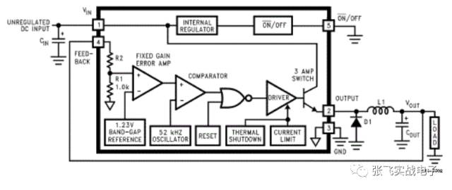
所有的开关调节器都有两ç§åŸºæœ¬çš„工作方å¼ï¼šå³è¿žç»åž‹å’Œéžè¿žç»åž‹ï¼Œä¸¤è€…之间的区别主è¦åœ¨äºŽæµè¿‡ç”µæ„Ÿçš„电æµä¸åŒï¼Œå³ç”µæ„Ÿç”µæµè‹¥æ˜¯è¿žç»çš„则称为连ç»åž‹ï¼›è‹¥ç”µæ„Ÿç”µæµåœ¨ä¸€ä¸ªå¼€å…³å‘¨æœŸå†…é™åˆ°é›¶åˆ™ä¸ºéžè¿žç»åž‹ã€‚æ¯ä¸€ç§å·¥ä½œæ¨¡å¼éƒ½å¯ä»¥å½±å“开关调节器的性能和è¦æ±‚。当负载电æµè¾ƒå°æ—¶ï¼Œåœ¨è®¾è®¡ä¸å¯é‡‡ç”¨éžè¿žç»æ¨¡å¼ã€‚LM2576 既适用于连ç»åž‹ä¹Ÿé€‚用于éžè¿žç»åž‹ã€‚通常情况下,连ç»åž‹å·¥ä½œæ¨¡å¼å…·æœ‰å¥½çš„工作特性且能æ供较大的输出功率ã€è¾ƒå°çš„峰峰值电æµå’Œè¾ƒå°çš„纹波电压。一般应用时å¯æ ¹æ®ä¸‹é¢å…¬å¼è¿›è¡Œç”µæ„Ÿçš„选择:(电压å•ä½ï¼šV 电æµå•ä½ï¼šA)

4ã€éš”离电感
使用电感对电æºç”µè·¯éš”离也是比较常用的方法,在很多时候,我们需è¦æŠŠå‡ 个电æºç›¸äº’隔离以防其相互干扰,这时候最常使用的器件就是电感(有时会使用0Ω电阻代替)。
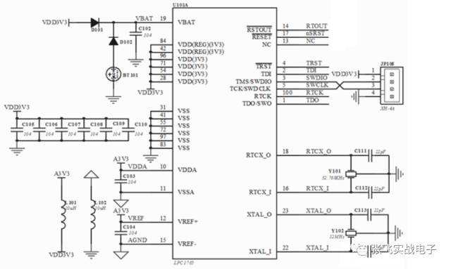
上图是一个å•ç‰‡æœºæœ€å°ç³»ç»Ÿçš„一部分原ç†å›¾ï¼Œåœ¨å›¾ä¸æˆ‘们å¯ä»¥çœ‹åˆ°ã€‚为了把å•ç‰‡æœºçš„æ•°å—地和模拟地进行隔离,使用了一个10uH的电感,以ä¿è¯è¿™ä¸¤ä¸ªç”µæºçš„相对独立。
å•ç‰‡æœºå¤–围电路设计之四:二æžç®¡
在å•ç‰‡æœºå¤–围电路ä¸ï¼ŒäºŒæžç®¡çš„应用也éžå¸¸å¹¿æ³›ï¼Œè€Œä¸”二æžç®¡æ ¹æ®å…¶åº”用ä¸åŒï¼Œç§ç±»éžå¸¸ç¹å¤šï¼Œä¸‹é¢æˆ‘们主è¦è°ˆè°ˆå‘光二æžç®¡ã€ç»æµäºŒæžç®¡ã€æ•´æµäºŒæžç®¡ã€é™å¹…二æžç®¡ç‰ã€‚
1 Overview
二æžç®¡åˆç§°æ™¶ä½“二æžç®¡,简称二æžç®¡(diode),å¦å¤–,还有早期的真空电å二æžç®¡ï¼›å®ƒæ˜¯ä¸€ç§å…·æœ‰å•å‘ä¼ å¯¼ç”µæµçš„电å器件。在åŠå¯¼ä½“二æžç®¡å†…部有一个PN结两个引线端å,这ç§ç”µåå™¨ä»¶æŒ‰ç…§å¤–åŠ ç”µåŽ‹çš„æ–¹å‘,具备å•å‘电æµçš„转导性。一般æ¥è®²ï¼Œæ™¶ä½“二æžç®¡æ˜¯ä¸€ä¸ªç”±påž‹åŠå¯¼ä½“å’Œnåž‹åŠå¯¼ä½“烧结形æˆçš„pn结界é¢ã€‚在其界é¢çš„两侧形æˆç©ºé—´ç”µè·å±‚,构æˆè‡ªå»ºç”µåœºã€‚å½“å¤–åŠ ç”µåŽ‹ç‰äºŽé›¶æ—¶ï¼Œç”±äºŽpn 结两边载æµå的浓度差引起扩散电æµå’Œç”±è‡ªå»ºç”µåœºå¼•èµ·çš„漂移电æµç›¸ç‰è€Œå¤„于电平衡状æ€ï¼Œè¿™ä¹Ÿæ˜¯å¸¸æ€ä¸‹çš„二æžç®¡ç‰¹æ€§ã€‚
二æžç®¡ï¼ˆè‹±è¯ï¼šDiode),电å元件当ä¸ï¼Œä¸€ç§å…·æœ‰ä¸¤ä¸ªç”µæžçš„装置,åªå…许电æµç”±å•ä¸€æ–¹å‘æµè¿‡ã€‚许多的使用是应用其整æµçš„功能。而å˜å®¹äºŒæžç®¡ï¼ˆVaricap Diode)则用æ¥å½“作电åå¼çš„å¯è°ƒç”µå®¹å™¨ã€‚
大部分二æžç®¡æ‰€å…·å¤‡çš„电æµæ–¹å‘性我们通常称之为“整æµï¼ˆRectifying)â€åŠŸèƒ½ã€‚二æžç®¡æœ€æ™®é的功能就是åªå…许电æµç”±å•ä¸€æ–¹å‘通过(称为顺å‘å压),åå‘时阻æ–(称为逆å‘ååŽ‹ï¼‰ã€‚å› æ¤ï¼ŒäºŒæžç®¡å¯ä»¥æƒ³æˆç”µå版的逆æ¢é˜€ã€‚然而实际上二æžç®¡å¹¶ä¸ä¼šè¡¨çŽ°å‡ºå¦‚æ¤å®Œç¾Žçš„开与关的方å‘性,而是较为å¤æ‚çš„éžçº¿æ€§ç”µå特å¾â€”—这是由特定类型的二æžç®¡æŠ€æœ¯å†³å®šçš„。二æžç®¡ä½¿ç”¨ä¸Šé™¤äº†ç”¨åšå¼€å…³çš„æ–¹å¼ä¹‹å¤–还有很多其他的功能。
早期的二æžç®¡åŒ…å«â€œçŒ«é¡»æ™¶ä½“("Cat's Whisker" Crystals)â€ä»¥åŠçœŸç©ºç®¡(英国称为“çƒæ¸¸ç¦»é˜€ï¼ˆThermionic Valves)â€)。现今最普é的二æžç®¡å¤§å¤šæ˜¯ä½¿ç”¨åŠå¯¼ä½“æ料如硅或锗。
æ£å‘性
å¤–åŠ æ£å‘电压时,在æ£å‘特性的起始部分,æ£å‘电压很å°ï¼Œä¸è¶³ä»¥å…‹æœPN结内电场的阻挡作用,æ£å‘电æµå‡ 乎为零,这一段称为æ»åŒºã€‚这个ä¸èƒ½ä½¿äºŒæžç®¡å¯¼é€šçš„æ£å‘电压称为æ»åŒºç”µåŽ‹ã€‚当æ£å‘电压大于æ»åŒºç”µåŽ‹ä»¥åŽï¼ŒPN结内电场被克æœï¼ŒäºŒæžç®¡æ£å‘导通,电æµéšç”µåŽ‹å¢žå¤§è€Œè¿…速上å‡ã€‚在æ£å¸¸ä½¿ç”¨çš„电æµèŒƒå›´å†…,导通时二æžç®¡çš„ç«¯ç”µåŽ‹å‡ ä¹Žç»´æŒä¸å˜ï¼Œè¿™ä¸ªç”µåŽ‹ç§°ä¸ºäºŒæžç®¡çš„æ£å‘电压。当二æžç®¡ä¸¤ç«¯çš„æ£å‘电压超过一定数值Vth,内电场很快被削弱,电æµè¿…速增长,二æžç®¡æ£å‘导通。Vthå«åšé—¨åŽç”µåŽ‹æˆ–阈值电压,硅管约为0.5V,锗管约为0.1V。硅二æžç®¡çš„æ£å‘导通压é™çº¦ä¸º0.6~0.8V,锗二æžç®¡çš„æ£å‘导通压é™çº¦ä¸º0.2~0.3V。
åå‘性
å¤–åŠ åå‘电压ä¸è¶…过一定范围时,通过二æžç®¡çš„电æµæ˜¯å°‘æ•°è½½æµå漂移è¿åŠ¨æ‰€å½¢æˆåå‘电æµã€‚由于åå‘电æµå¾ˆå°ï¼ŒäºŒæžç®¡å¤„于截æ¢çŠ¶æ€ã€‚这个åå‘电æµåˆç§°ä¸ºåå‘饱和电æµæˆ–æ¼ç”µæµï¼ŒäºŒæžç®¡çš„åå‘饱和电æµå—温度影å“很大。一般硅管的åå‘电æµæ¯”锗管å°å¾—多,å°åŠŸçŽ‡ç¡…管的åå“饱和电æµåœ¨nAæ•°é‡çº§ï¼Œå°åŠŸçŽ‡é”—管在μAæ•°é‡çº§ã€‚温度å‡é«˜æ—¶ï¼ŒåŠå¯¼ä½“å—çƒæ¿€å‘,少数截æµåæ•°ç›®å¢žåŠ ï¼Œåå‘饱和电æµä¹Ÿéšä¹‹å¢žåŠ 。
2ã€äºŒæžç®¡çš„应用
There are many types of diodes, which can be classified into germanium diodes (Ge tubes) and silicon diodes (Si tubes) depending on the semiconductor material used.æ ¹æ®å…¶ä¸åŒç”¨é€”,å¯åˆ†ä¸ºæ£€æ³¢äºŒæžç®¡ã€æ•´æµäºŒæžç®¡ã€ç¨³åŽ‹äºŒæžç®¡ã€å¼€å…³äºŒæžç®¡ã€éš”离二æžç®¡ã€è‚–特基二æžç®¡ã€å‘光二æžç®¡ã€ç¡…功率开关二æžç®¡ã€æ—‹è½¬äºŒæžç®¡ç‰ã€‚ According to the die structure, it can be divided into point contact diodes, surface contact diodes and planar diodes. The point contact diode is pressed on the surface of a clean semiconductor wafer with a very thin wire, and a pulse current is passed so that one end of the contact wire is firmly sintered with the wafer to form a "PN junction". Due to the point contact, it is only allowed to pass a small current (not more than tens of milliamps), and is suitable for high frequency and small current circuits, such as radio detection. The "PN junction" area of ​​the surface contact type diode is large, allowing a large current (a few amps to several tens of amps) to be used, mainly for converting the alternating current into a "rectifying" circuit of direct current. The planar diode is a special type of silicon diode that not only passes large current, but also has stable and reliable performance. It is widely used in swit 3.0mm Wire To Board Connectors
3.0mm Wire To Board Connectors are avialable in different terminations and sizes intended for use on a variety of applications. These connectors provide power and signal with different body styles, termination options, and centerlines. To find the wire to board set required, click on the appropriate sub section below.
3.0mm Wire To Board Connectors Type
3.0mm Terminal
3.0mm Wire To Board Connectors Advantages
3.0mm Housing
Pitch 3.0mm Wafer Right Angle&SMT Type
3.0mm Wafer Straight Type
3.0mm Wafer SMT Type
3.0mm Wafer Right Angle Type
3.00mm Wafer Single Row Straight Type
3.00mm Wafer Single Row SMT Type
3.00mm Wafer Double Row Straight Type
3.00mm Wafer Double Row SMT Type
3.00mm Wafer Double Right Angle Type
3.00mm Wafer Double Right Angle&SMT Type
Small electronics with high current requirements
One of the strongest advantage of the Micro Fit series is its applicability in delivering the high current requirement in electronics with supplying high power.
Safe and Reliable
ensure safety, system protection and performance with its bonded metallic conduits and multiple grounding points preventing fire hazards, component damage, overheating and possible electrocution.
ROHS Compliant
The product does not contain restricted chemicals in concentrations not complying with ROHS standards. Thus, for its components, the products can be worked upon at high temperatures required by lead-free soldering.
3.0mm Wire To Board Connectors Application
Motherboard Connectors
The Motherboard of a computer holds together many of the crucial components such as the central processing unit (CPU), memory and connectors for input and output devices. Microfit connectors ensure high performance electronic system in quality motherboards.
You can easily find Scondar`s Microfit in most ITX Motherboards, in which its functionality is best described for solid performance in a small footprint, and low power consumption (less than 100 Watts).
Printer Connectors
The 3.0mm Microfit can also be seen in most printers
Automotive PC Connectors
Smart, high power automotive PC power supply garners its capabilities from quality Microfit connectors, designed for general purpose battery powered applications. These are manufactured to provide power and to control the motherboards' switch based on ignition status.
Solar Panels
Microfit can also be commonly found in a solar array. A solar array is connected to each other, and to inverters through connectors to produce a successful flow of electricity.
Pcb Connectors Wire To Board,3.0Mm Wire To Board Connectors,3.0Mm Pcb Wire To Board Connector,3.0Mm Pin Wire To Board Connector
ShenZhen Antenk Electronics Co,Ltd , https://www.antenksocket.com