If you have a voltage divider, each of which supports a drift of 5 ppm/°C, what is the worst case drift? This is a question I have put forward to my colleagues when I recently studied the low drift current sensing reference design (TIPD156) (of course, after I have already come up with the answer). The "obvious" answer is 10ppm/°C. The real answer is actually only 5ppm/°C, but must it be in the voltage divider ratio? when. Let's take a closer look at the answer to this obvious problem that is not obvious.
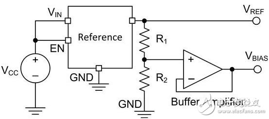
Figure 1 is a discrete solution that provides a reference voltage (VREF) and a bias voltage (VBIAS) based on the R1 to R2 ratio.

Figure 1: Dual Reference Discrete Topology
At this point, the overall drift of the “apparent†resistor divider is (5 ppm/°C) + (5 ppm/°C) = 10 ppm/°C. I made a simulation for confirmation. Figure 2 shows the results of the TINA-TI simulation, where R2 drifts in the positive direction, R1 drifts in the negative direction, and the temperature change is 100 °C.

Figure 2: Vbias after R1 and R2 drift
The calculated gain error is 0.05% (500 ppm or 5.0 ppm/°C). This is a drift of resistors, not their sum!
Now let's take a look at the gain ratio of a common voltage divider circuit and rearrange it according to equation (1).

among them

a is the ratio of R1 to R2 and is ultimately related to the gain of the circuit. For example, if α=1, what is the gain? . Then, when α→0, the gain →1. Similarly, when α→∞, the gain →0.
The actual gain of the circuit at different temperatures will depend on the drift of the resistor, expressed as δ in equation (3). In order to be consistent with the simulation, R2 drifts in the positive direction and R1 drifts in the negative direction.

Equation (4) calculates the gain error. For the sake of simplicity, it is not converted to a percentage (if you want to convert, just multiply by 100, but be careful when converting to ppm).

Using equations (1) through (3), equation (4) can be simplified to:

Note that the gain error is determined by the drift (δ) and the circuit gain (related to α). In addition, if α = 1 (circuit gain = ?), the gain error can be reduced to δ, which is exactly the result of the simulation display!
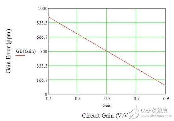
Figure 3 is a comparison of the design gain error versus circuit gain (5ppm/°C resistor drift, or 500ppm total drift at 100°C). Note that when the circuit gain is? At the time, the gain error is 500 ppm. Also note that as the circuit gain increases, the gain error decreases and vice versa.

In summary, the drift of the voltage divider is different than expected. It is not a simple addition, but depends on the gain of the circuit. So, the next time you design your circuit, if you come up with an "obvious" conclusion, you might want to use TINA-TI to verify it!
ZGAR Aurora 2500 Puffs
ZGAR electronic cigarette uses high-tech R&D, food grade disposable pod device and high-quality raw material. All package designs are Original IP. Our designer team is from Hong Kong. We have very high requirements for product quality, flavors taste and packaging design. The E-liquid is imported, materials are food grade, and assembly plant is medical-grade dust-free workshops.
Our products include disposable e-cigarettes, rechargeable e-cigarettes, rechargreable disposable vape pen, and various of flavors of cigarette cartridges. From 600puffs to 5000puffs, ZGAR bar Disposable offer high-tech R&D, E-cigarette improves battery capacity, We offer various of flavors and support customization. And printing designs can be customized. We have our own professional team and competitive quotations for any OEM or ODM works.
We supply OEM rechargeable disposable vape pen,OEM disposable electronic cigarette,ODM disposable vape pen,ODM disposable electronic cigarette,OEM/ODM vape pen e-cigarette,OEM/ODM atomizer device.

Aurora 2500 Puffs,ZGAR Aurora 2500 Puffs Pod System Vape,ZGAR Aurora 2500 Puffs Pos Systems Touch Screen,ZGAR Aurora 2500 Puffs Disposable Vape Pod System,2500Puffs Pod Vape System
Zgar International (M) SDN BHD , https://www.zgarecigarette.com