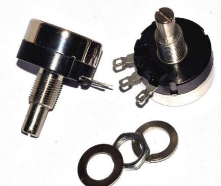
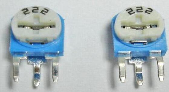
Adjustable resistance is also called variable resistance. Its English is Rheostat. Adjustable resistance is a type of resistance. The resistance value of adjustable resistance can be adjusted artificially to meet the needs of the circuit.
Adjustable resistors can be divided into many different models and types according to the size of the resistance value, the range of adjustment, the form of adjustment, the production process, the production material, the size, etc., which can be divided into: adjustable resistors for electronic components, adjustable ceramic plates Resistors, patch adjustable resistors, wire wound adjustable resistors and so on.
The nominal value of the adjustable resistor is the standard that can be adjusted to the maximum resistance value. In theory, the resistance of the adjustable resistor can be adjusted to any value within 0 and the nominal value, but because of the actual structure and design accuracy requirements, etc. The reason is that it is often not easy to meet the "arbitrary" requirements 100%, but "basically" adjust within the allowable range to change the resistance.
Wiring method of adjustable resistorThere are two connection methods: varistor type and voltage regulating type.
1. Variable resistance
The variable resistance type is that one fixed point is connected to the 0 position, and the other fixed point is connected to the voltage, so that the adjustable voltage can be output between the 0 position fixed point and the movable head;
2. Pressure regulating type
The voltage regulating type is a fixed point and the movable head short-circuit, so that the resistance between the two fixed points becomes a changeable resistance.

The adjustable resistor generally has 3 terminals, the left and right two are fixed, and the resistance between them is the resistance of the adjustable resistor. The first terminal is connected to the movable arm pin in the middle of the resistor, and its function is to adjust the resistance. Then the remaining two connecting terminals are connected to the remaining left and right pins, and the two fixed terminals of the adjustable resistor are connected in series in the circuit to change the resistance value.

step one
First, use a flat-blade screwdriver to reach the adjustment port of the resistor. The screwdriver can be rotated clockwise or counterclockwise to adjust. At this time, the moving piece of the resistor will also be rotated accordingly.
Step two
When turning clockwise to adjust, the resistance between the stator 1 and the stator will increase, and the resistance between the stator and the stator 2 will decrease. When the moving plate slides to the rightmost position, the resistance between the stator 2 and the pins of the moving plate is zero, and the resistance between the stator 1 and the moving plate is the largest.
Step three
When rotating counterclockwise to adjust, the length of the resistor between the stator 2 and the movable plate will increase, and the resistance will increase accordingly. If the length of the resistor body between the stator 1 and the rotor is reduced, the resistance value will also decrease subsequently. When the moving piece rotates to the leftmost position, the resistance value between the fixed piece 1 and the moving piece pin at this time is zero. And the resistance between the stator 2 and the pins of the movable plate is the largest, and at this time it is equal to the nominal resistance indicated by the adjustable resistor, which means that it is equal to the resistance between the two stators.
High resolution
In order to realize a large-area high-resolution Liquid Crystal Display, it is usually necessary to use low-impedance metal materials, high-performance switching elements, and high-precision processing techniques. Aluminum is the most researched and used material for making TFT buses with low-impedance metals. By solving the problems of easy formation of hillocks, chemical corrosion and oxidation of aluminum, alloy methods (such as Al-Cu, Al-Si, Al-Nd and Al-Ti, etc.) and interlayer methods (such as Mo/Al/Mo) have been reported successively. , Cr/Al/Cr and Ti/Al/Ti, etc.), the alloy method is relatively simple in process, but the material has a higher resistivity. In May 1998, IBM developed a 16.3-inch ultra-high resolution (200ppi) a-Si TFT Display using Al-Nd alloy as the gate electrode, and mass production has been achieved. In April 1999, Toshiba introduced the 20.8-inch 16-SVGA (3, 200 × 2, 400) a-Si TFT-LCD, which can be said to represent the highest level of a-Si TFT-LCD in terms of high resolution and high capacity. .
According to Display Search in the third quarter of 2011, the global flat panel display research report "QuarterlyWorldw ide Flat Pane l Dis play Fore cas t Re port" pointed out that the average pixels per inch (ppi) in large-size LCD panels (>9.1 inches) ) Will grow from 88ppi in 2010 to 98ppi in 2015. The ppi of small and medium-sized LCD panels (<9.0 inches) will grow from 180ppi to 300ppi in the same period. With the rise of smart phones, mobile phones will be the most obvious application product for ppi's growth.
Another important way to realize high-resolution liquid crystal display is to develop LT p-Si TFT technology. The resolution of published p-SiTFT-LCD products is generally around 200ppi. Compared with a-Si TFT-LCD, LT p-Si TFT-LCD has a smaller volume of thin film transistors and storage capacitors. Therefore, it has a larger penetration area per inch, resulting in a brighter display. , And save more power. When the market demands higher ppi, low-temperature polysilicon (LTPS) technology becomes the best choice for manufacturing high-resolution thin-film transistor liquid crystal displays.
Contrast
The control ICs, filters and oriented films used in LCD manufacturing are related to the contrast of the panel. For general users, a contrast ratio of 350:1 is sufficient, but such contrast in the professional field does not satisfy users. Demand. Compared with CRT monitors easily reaching 500:1 or even higher contrast, only high-end LCD monitors can achieve this level. The first-tier LCD monitors on the market, such as Samsung, Asus, LG, etc., can reach a contrast ratio of 1000:1. However, because the contrast is difficult to accurately measure with instruments, you have to go and see it yourself when you pick it.
Tip: Contrast is very important. It can be said that the selection of LCD is a more important indicator than bright spots. When you understand that your customers buy LCDs for entertainment and watching DVDs, you can emphasize that contrast is more important than no dead pixels. We When watching streaming media, the brightness of the source is generally not large, but to see the contrast of light and dark in the scene of the character, the texture change from gray to black hair must be shown by the level of contrast. The 256-level grayscale in the test software In the test, more small gray grids can be seen clearly when looking up, which means that the contrast is better!a
Lcd Display Module,Tft Lcd Screen Display,Display Lcd Enclosure,Tft Display Lvds
ESEN Optoelectronics Technology Co., Ltd, , https://www.esenoptoelectronics.com