The broadcast TV transmitter modulates the color full TV signal and the sound signal on the radio frequency carrier wave, and propagates it through the antenna in the form of high-frequency electromagnetic waves. The radio frequency carrier wave adopts the meter wave band (VHF band) and decimeter wave band (UHF band). ?
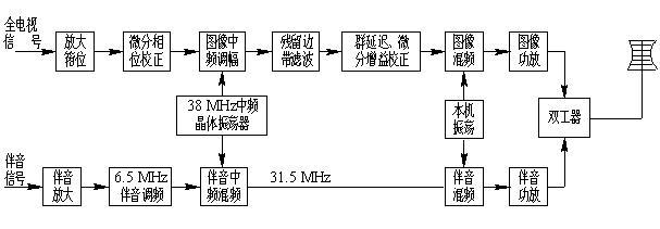
The TV transmitter is composed of an image transmitter and an audio transmitter, and is called a dual-channel TV transmitter. TV transmitters share a transmitter by image and sound, called single channel TV transmitter. Figure 4-5 is a block diagram of their composition principle. ??

(a) Dual channel TV transmitter; (b) Single channel TV transmitter

(a) Dual channel TV transmitter; (b) Single channel TV transmitter
Comparing the two component block diagrams, it can be seen that the image signal is amplitude-modulated at an intermediate frequency of 38 MHz. This has a great advantage in that the transmitter works on any channel and the front-end circuit is the same, which is convenient for production. ?
The working level of the intermediate frequency AM modulator is low, and it is more convenient to process and correct the signal, so the residual sideband filtering and differential gain correction are placed at the intermediate frequency. The residual sideband filter circuits of different working channels are the same, and the group delay error introduced by the residual sideband filter is also corrected at the intermediate frequency, and a good correction effect can be obtained. ?
After the residual sideband filtering, the two sidebands of the TV signal are asymmetric, which is likely to cause differential gain distortion in the high-frequency power amplifier. The differential gain distortion is more troublesome in video correction, so it is corrected at the intermediate frequency. ?
The sound signal is modulated on the second sound IF at 6.5 MHz, and then mixed with 38 MHz to obtain the sound IF 31.5 MHz signal more conveniently. ?
The dual-channel transmitter uses a duplexer after the high-frequency power amplifier to prevent mutual interference between the image and the audio signal. Due to the good matching between the transmitter, feeder and antenna, it can ensure high-frequency signal energy efficient and high-quality transmission. After the image and sound intermediate frequency signal of the single-channel transmitter are mixed, they are frequency-converted together, power-amplified together, and transmitted together, so the equipment is relatively simple. ??
China's television standards stipulate that the sound carrier frequency is 6.5 MHz higher than the image carrier frequency in the same channel. In order to ensure that the image and the audio can have the same coverage area, the ratio of the peak image power to the audio carrier frequency power is about 5: 1, and in a single-channel transmitter their power ratio is 10: 1.
Welcome to reprint, this article comes from the electronic fan network (http: //)?
High Quality Rectifier Diode with Competitive Price, Fast Shipping, Order Now.Years of experience.
The company has domestic advanced diode production equipment, complete testing methods and quality assurance system.
Advanced Technology.Electronic component diodes are widely used in household appliances, green lighting, network communications, power chargers, automotive electronics and other fields.

Rectifier Diode,diode Bridge Rectifier,KBU Bridge Rectifiers,rectifier diode,Fast rectifier diode
Changzhou Changyuan Electronic Co., Ltd. , https://www.changyuanelectronic.com