There are various forms of waves in nature, such as ocean waves, earthquakes, sound waves, blasting, sound propagating in the air, or natural rhythms of body movement. In the physical world, energy, vibrating particles, and invisible forces are everywhere. Even light (wave-particle duality matter) has its own frequency and shows different colors because of the difference in frequency.
OscilloscopeAn oscilloscope is a must-have for any design, manufacture or maintenance of electronic equipment. In today's world that changes instantly, engineers need the best tools to solve measurement problems quickly and accurately.
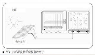
The use of oscilloscopes is not limited to the electronics field. Oscilloscopes use signal converters and are suitable for various physical phenomena. The signal converter can respond to various physical excitation sources and convert it into electrical signals, including sound, mechanical stress, pressure, light, and heat. The microphone is a signal converter, which converts sound into electrical signals. An example of scientific data collected by an oscilloscope is shown in Figure 1.

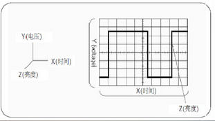
The oscilloscope is a waveform display instrument that vividly displays the change of signal amplitude with time. It is a comprehensive signal characteristic tester and a basic electronic measuring instrument. It depicts the graphic curve of the electrical signal. In most applications, the graphs presented can show how the signal changes over time: the vertical (Y) axis represents voltage, and the horizontal (X) axis represents time. The brightness is sometimes called the Z axis. (Refer to Figure 2)

Electronic equipment can be divided into two categories: analog equipment and digital equipment. The voltage of the analog device changes continuously, while the digital device deals with discrete binary codes that represent voltage samples. The traditional record player is an analog device, while the CD player is a digital device.
Similarly, oscilloscopes can also be divided into analog and digital types. Both analog and digital oscilloscopes are capable of most applications. However, for some specific applications, due to the different characteristics of the two, each type has its suitable and unsuitable places. For advanced division, digital oscilloscopes can be divided into digital storage oscilloscopes (DSO), digital phosphor oscilloscopes (DPO) and sampling oscilloscopes.
Analog oscilloscope
In essence, the analog oscilloscope works by directly measuring the signal voltage and plotting the voltage in the vertical direction through an electron beam passing through the oscilloscope screen from left to right. The oscilloscope screen is usually a cathode ray tube (CRT). When the electron beam is projected somewhere on the screen, there will always be bright fluorescent material behind the screen. When the electron beam sweeps horizontally across the display, the signal voltage is that the electron beam deflects up and down, and the tracking waveform is directly reflected on the screen. The more frequently the electron beam is projected at the same position on the screen, the brighter the display.
CRT limits the frequency range displayed by an analog oscilloscope. In places where the frequency is very low, the signal shows bright and slowly moving points, and it is difficult to distinguish the waveform. At high frequencies, the limitation is the writing speed of the CRT. When the signal frequency exceeds the writing speed of the CRT, the display is too dim and difficult to observe. The limit frequency of the analog oscilloscope is about 1CHz.
When the oscilloscope probe and the circuit are connected together, the voltage signal passes through the probe to the vertical system of the oscilloscope. Figure 13 describes how the analog oscilloscope displays the signal under test. After setting the vertical scale (controlling volts/div), the attenuator can be a small signal voltage, and the amplifier can increase the signal voltage. Subsequently, the signal directly reaches the vertical deflection plate of the CRT. Voltage is applied to these vertical deflection plates, causing bright spots to move in the screen. The bright spot is produced by the electron beam hitting the fluorescent substance inside the CRT. A positive voltage causes the point to move up, while a negative voltage causes the point to move down.
Digital oscilloscope
Unlike an analog oscilloscope, a digital oscilloscope converts the measured voltage into digital information through an analog-to-digital converter (ADC). It captures a series of samples of the waveform and stores the samples. The storage limit is to judge whether the accumulated samples can draw the waveform. Subsequently, the digital oscilloscope reconstructs the waveform.
Digital oscilloscopes are divided into digital storage oscilloscopes (DSO), digital phosphor oscilloscopes (DPO) and sampling oscilloscopes.
The digital means mean that within the scope of the oscilloscope, waveforms of any frequency can be displayed stably, brightly and clearly. For repetitive signals, the bandwidth of a digital oscilloscope refers to the analog bandwidth of the front-end components of the oscilloscope, which is generally called the 3dB point. For single pulse and transient events, such as pulses and step waves, the bandwidth is limited to the oscilloscope's sampling rate.
Hp Laptop 15S-Du 15S-Dy 15-Dw,Hp Laptop Top Cover,Hp Laptop Bottom Case,Hp15 Bottom Case
S-yuan Electronic Technology Limited , https://www.syuanelectronic.com