In an embedded system using a front-back system software design pattern, the main program is an infinite loop, single-task sequential execution, and asynchronous events are handled by setting one or more interrupts. This kind of system can be used for simple applications. However, for applications that require high real-time performance and have more processing tasks, they will expose shortcomings such as poor real-time performance, low system reliability, and poor stability. μC/OS-II is a source code open, portable, and can be tailored for multiple real-time tasks
The operating system has the advantages of low cost, stability, reliability, real-time performance, etc. It is a real-time kernel specifically designed for microprocessors and microcontrollers. Its kernel can be very small and is suitable for porting on a single-chip microcomputer system. The embedded μC/OS-II embedded system can make each task work independently without interfering with each other. It is easy to implement punctual and error-free execution, which makes the design and expansion of real-time applications easier, and makes the application design process much easier. Reduced. this
Freescale's 16-bit microcontroller MC9S12DG128 was selected as the hardware platform, and the μC/OS-II source code was rewritten accordingly for the MC9S12DG128 memory organization and architecture.
Now port the μC/OS-II operating system on the MC9S12DG128. By porting μC/OS-II on MC9S12DG128, you can master the essence of porting and testing μC/OS-II, and it is easy to migrate it to other CPU platforms.
2 MC9S12DG128 architecture (memory organization)The authors believe that a deep understanding of the architecture and memory organization of the MC9S12DG128 microcontroller is a key step in the success of the migration. The MC9S12DG128 is a 16-bit, high-performance microcontroller with very low power consumption and up to
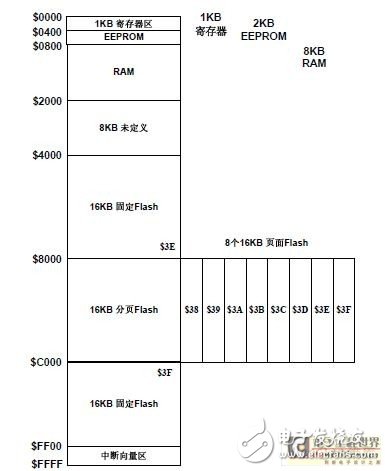
With an internal bus frequency of 25MHz, on-chip resources include 1KB of internal registers, 8KB of RAM, 128KB of FLASH, and 2KB of EEPROM. The MC9S12DG128 uses a Princeton bus architecture. The program memory, data memory, and I/O ports are addressed in a unified manner. The total address space is 64 KB. However, there are 128 KB Flashes in the DG128. Obviously, the memory space exceeds the addressable 64 KB of the S12 MCU. Therefore, the page access mechanism was introduced. The S12CPU opened a window in the section of memory from $8000 to $BFFF. There are eight 16KB pages (where $3E and $3F have fixed addresses), which can be selected through the page register (PPAGE). One of the pages. For memory areas other than 64 KB, the application-specific instruction CALL calls the subroutine and then returns with the RTC instruction.
The different memory inside the microcontroller occupies different storage space, that is, different address ranges, they occupy a specific address space, the address allocation of these memory and internal integrated modules is not fixed, the user can re- Assign, but do not easily modify the default mapping space, should use the default address mapping space. Figure 1 shows the memory space allocation after MC9S12DGl28 reset. Among them, the address $0000 ~ $03FF is 1KB register space; $0000 ~ $1FFF is 8KB RAM (visible 7KB); $0000 ~ $07FF is 2KBEEPROM (not visible).

Figure 1 Memory space distribution after MC9S12DGl28 reset
You can reassign the location of each memory by setting the INITRG, INITRM, and INIteE registers. These registers can only be written once. It is recommended to allocate memory locations during initialization. If there is address overlap in the mapping, the priority control logic inside the S12CPU automatically shields lower-level resources and reserves the highest-level resources. Registers have the highest priority, and overlapping RAM and EEPROM are invalid at this time. The memory priority is listed in the following table.
Transplantation of 3 μC/OS-II on MC9S12DG128μC/OS-II requires a portion of ROM and RAM space while running, but μC/OS-II OS kernel target code can be cut to less than 2KB. MC9S12DG128 has 8KB of RAM memory and 128KB of Flash memory.
Memory, so the μC/OS-II operating system is fully portable and runs on the MC9S12DG128.
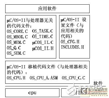
The 95% code of μC/OS-II is written by ANSI C and has good portability. To realize μC/OS-II migration to S12, the main work is to do two aspects: first, redefine the size and function of the kernel; second, write hardware-related code for the kernel. The file structure of μC/OS-II is shown in Figure 2.

Figure 2 File Structure of μC/OS-II
It can be seen that μC/OS-II C code files irrelevant to the CPU type include many files, which are the μC/OS-II kernel and many function functions, among which OS_CORE.C, OS_TIME.C, and OS_TASK.C Files must be used. Other files are used for communication between tasks. Only a few of them may be used in an application. Those that are not needed may not be included in order to avoid code generation during compilation. This part of the code has nothing to do with the type of CPU, these files do not move at the time of transplantation.
The code files related to the CPU type mainly include: OS_CFG.H, OS_CPU.H, OS_CPU_A.ASM, and OS_CPUC.C. OS_CFG.H is a configuration file and needs to be configured according to the application. The main function is to determine which system function functions are provided by the user application using μC/OS-II. This file must be modified when the file is migrated. The OS_CPU.H file defines the data types used for a specific CPU and defines the related macros. OS_CPU_A.ASM is hardware-related code written in assembly language, and OS_CPUC.C file is hardware-related code written in C language. If the C cross-compilation tool used for migration can insert assembler statements in the C code, the OS_CPU_A.ASM can be combined into the S_CPUC.C file during migration.
3.1 Redefining the Size and Function of the Kernel
The public header file INCLUDES.H, which is referenced by all C source programs. The code for this file in this example is as follows.
#include
#include
#include
#include
#include
#include
#include
The first four header files are C function libraries, predefined types, etc., and have nothing to do with porting. Whether or not they must be added depends on the compiler used. The first three header files must be referenced, users can add their own header files, but they must be put
At the end.
The file that needs to be modified according to the application is OS_CFG.H, which is used to configure the properties of the kernel. Used to set properties related to the microcontroller CPU core, including the storage lengths for various data types, and so on. OS_CPU.H includes processor-related constants, macros, and types as defined by the #define statement. Because different processors have different word sizes, μC/OS-II's porting includes a series of data type definitions to ensure portability. The μC/OS-II code does not use data types such as short, int, and long in the language because they are compiler-specific and non-portable. The use of defined shaped data structures is both portable and intuitive.
Typedef unsigned char BOOLEAN; /* Boolean variable */
Typedef unsigned char INT8U; /* unsigned 8-bit integer variable */
Typedef signed char INT8S; /* signed 8-bit integer variable */
Typedef unsigned int INT16U; /* unsigned 16-bit integer variable */
Typedef signed int INT16S; /* signed 16-bit integer variable */
......
The user must also tell the μC/OS-II the data type of the task stack. The stack of the S12CPU is 16-bit, so define OS_STK as INT16U. All task stacks must use OS_STK to declare data types.
#define OS_STK INT16U /* The stack is 16 bits wide */
For different processors, the direction of the stack pointer grows differently when the data is loaded into the stack. The stack pointer of the MC9S12DG128 microcontroller is incremented from a high address to a low address. Therefore, the stack must be set in advance.
Growth direction:
#define OS_STK_GROWTH 1 /* The stack pointer grows from high address to low address */
μC/OS-II needs to first disable interrupts and then access critical sections of the code, and re-enable interrupts after the access is complete. This allows μC/OS-II to protect the critical section code from being disrupted by multitasking or interrupt service routines. The macros that disable and allow interrupts are OS_ENTER_CRITICAL() and OS_EXIT_CRITICAL(). There are three methods for defining these two macros. The method used for migration is method 1, and the interrupt is turned off before entering the critical code, and the interrupt is opened after leaving the critical code [2]. Method 1 is defined in OS_CPU.H like this:
#if OS_CRITICAL_METHOD == 1 //Method One
#define OS_ENTER_CRITICAL( ) asm SEI
#defien OS_EXIT_CRITICAL () asm CLI
#endif
3.2 Writing Hardware-Related Code
Next you need to write hardware-related code. This part of the code can use C language, can also use assembly language. The most important hardware-related files in the migration are OS_CPU_C.C and the assembly file OS_CPU_A.ASM. Since the migration uses the CodeWarrior CW12 V4.6 version of the C cross-compilation tool provided by Metrowerks, and CW12 V4.6 allows assembly of assembly statements in the C code, the file OS_CPU_A.ASM can be merged.
Go to the OS_CPU_C.C file. The following is a specific process of transplantation.
3.2.1 Interrupt Service Routine OSTickISR()
The interrupts used by the interrupt service routines can be generated with the real-time clock or can be generated with the on-chip timer module. The transplant uses an analog-to-digital counter to generate accurate clock beat interrupts. The S12's modulo counter can be used to achieve an exact interrupt at any time. The interrupt here is 30 times per second.
When a clock tick interrupt occurs, the CPU 12 automatically pushes the CPU register onto the stack and then clears the interrupt flag. However, the page register PPAGE is not pushed onto the stack. If the CPU12's address range exceeds 64KB, PPAGE must also be pushed onto the stack. The PPAGE register is not used in this document.
The clock tick interrupt service routine may activate a task that has a higher priority than the currently interrupted task. The clock tick interrupt service routines are called consecutively: OSIntEnter(), OSTierTick() and OSIntExit()
These three functions. OSIntEnter() informs μC/OS-II to enter the interrupt service routine. OSTimerTick() decrements the task delay counter that requires a delay of several clock ticks. After decrementing by 1, the task is ready to go.
The OSIntExit() function tells the μC/OS-II clock tick service routine to end. If a higher-priority task enters the ready state at this time, OSIntExit() will call the interrupt-level task switching function OSIntCtxSw().
Do task switching so that higher priority tasks run. The following is the function code:
Void OSTickISR(void)
{
/* Decide whether to save PPAGE register according to need, there is no save */
OSIntEnter();
MCFLG_MCZF=1; // clear the modulo counter interrupt flag
OSTimeTick();
OSIntExit(); // Exit the interrupt and perform task switching
}
3.2.2 Task Stack Initialization Function OSTaskStkInit()
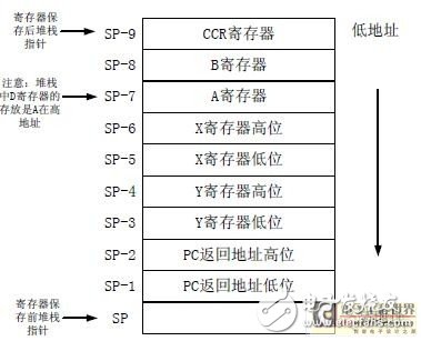
The functions written in this C language are related to the CPU hardware. This function initializes the task's stack, which is called by the task-building function OSTaskCreate() or by the extended setup task function OSTaskCreatExit(). The function to create a task has 4 formal parameters, and the extended function to create a task has 8 parameters. Where pdata is used to pass parameters to the task. This parameter is used to pass the page register PPAGE parameter to the created task. When rewriting the function, it is necessary to deeply understand the sequence of the CPU register's stacking when the interrupt occurs. Otherwise, μC/OS-II cannot be run. The sequence in which S12CPU registers are stacked when the interrupt occurs is shown in Figure 3. Since this function is called by the function that created the task, the initial value of each CPU register is not important. However, the contents of the CCR register need to pay attention: if the interrupt is enabled after the task is started, all interrupts are allowed during the task execution. Similarly, if the interrupt is disabled after the task is started, all tasks are prohibited from interrupting. Selected. This article chooses to turn on interrupts when the task starts. The following is the function code:
Void *OSTaskStkInit (void (*task)(void *pd), void *pdata, void *ptos, INT16U opt)
{
INT16U *stk;
Pt = opt; // 'opt' is not used, this prevents compiler warnings
Stk = (INT16U *)ptos; //Load stack pointer
*--stk = (INT16U)(pdata); //Place the parameter pdata passed to the function
*--stk = (INT16U)(task); //Function return address PC
*--stk = (INT16U)(0x1122); //register Y
*--stk = (INT16U)(0x3344); //register X
((INT8U *)stk)--; // Register A requires only 1 byte
*(INT8U *)stk = (INT8U)(0x55); //Register A
((INT8U *)stk)--; // Register B requires only 1 byte
*(INT8U *)stk = (INT8U)(0x66); //Register B
((INT8U *)stk)--; // Register CCR requires only 1 byte
*(INT8U *)stk = (INT8U)(0x00); // Register CCR, ON interrupt
Return ((void *)stk);
}
3.2.3 Let the highest priority ready state task run OSStartHightRdy()
OSStartHighRdy() is called by OSStart() when multitasking is started. After μC/OS-II finishes all initialization work, OSStart() starts multitasking, and OSStart() calls OSStartHighRdy().
The function runs the highest priority task among multiple ready tasks. Note that the stack pointer is always stored at the beginning of the task control block.

Figure 3 Sequence of S12CPU register stacking when an interrupt occurs
OSStartHighRdy() changes the value of the stack pointer SP of the CPU to the value of the stack pointer of the highest priority ready state task, and then changes the state word of the task from the non-operation state "FALSE" to the operating state "TRUE". then
Performing an interrupt returns the instruction RTI to start running this task. The following is the detailed code:
Void OSStartHighRdy(void)
{
OSTaskSwHook(); //call the hook function
Asm{
Ldx OSTCBCur // Load OSTCBCur address to x
Lds 0,x //Load OSTCBStrPtr to stack pointer sp
Ldaa OSRunning
Inca // SRunning = TRUE
Staa OSRunning
Rti
}
}
3.2.4 task-level task switching function OSCtxSw() and interrupt-level task switching function OSIntCtxSw()
Task-level switching is achieved by executing soft interrupt instructions. OSCtxSw() is actually a soft interrupt service routine. The vector address of the soft interrupt service routine points to OSCtxSw(). If the current task calls μC/OS-II
With the provided function and making the higher priority task ready, μC/OS-II will find OSCtxSw() with the vector address mentioned above. At the end of the system service call, μC/OS-II calls the task scheduler
Count OSSched() and infer from it that the current task is no longer the most important task to run.
Most of the code in the OSIntCtxSw() function is the same as the OS_TASK_SW() function. The interrupt exit function is to perform the switch function from the ISR through the function OSIntCtxSw(), the only difference is that the ISR has been saved.
The register of the CPU, it is no longer necessary to save the CPU's register in the OSIntCtxSw() function. The following only gives the task-level task switching function OSCtxSw() code:
Void OSCtxSw(void)
{
Asm{
Ldx OSTCBCur // Load the stack pointer of the current task
Sts 0,x // Save to the current task's TCB
}
OSTaskSwHook(); //call the hook function
STCBCur = OSTCBHighRdy; // Change the OSTCBCur and OSPrioCur of the task
SPrioCur = OSPrioHighRdy;
Asm{
Ldx OSTCBCur // Get stack pointer for new task
Lds 0,x // Load the new task's stack pointer to sp
Rti
}
}
4 Testing of transplant codeIn order to verify the correctness of the transplantation results, the μC/OS-II code after transplantation was tested, which is an important part of the transplantation. First, the kernel's own operation was tested, and the kernel itself was working properly.
After that, three more tasks are created: Task 1 Lights up the LED through the PORTA port, the task runs once per second; Task 2 and Task 3 both output strings through the string, both of which are run every 2 seconds, and Through the semaphore to achieve
Mutual exclusion so that each character can complete the output of all characters each time it runs. The experimental test proves that under the management and scheduling of μC/OS-II, these three tasks can be run correctly and reliably.
5 SummaryThrough the transplantation of μC/OS-II on the MC9S12DG128, the understanding of μC/OS-II core working principle and task scheduling method is deepened, and the general method of μC/OS-II transplantation is mastered. The test result shows that the transplant code can be stable. Reliable operation, multi-task management and scheduling. The introduction of μC/OS-II real-time operating system can not only improve the real-time performance, reliability and stability of the system, but also improve the portability of application software and reduce the workload of developers.
M8 distribution box is a kind of industrial connector. It is a device that converts a power supply or data into a shunt and outputs multiple current or data signals. General M8 distribution box refers to the line socket for M8 or M12 specifications of the distribution box. The difference between it and the ordinary socket is that the power output of the ordinary socket is only positive and negative two levels, or there is a ground wire, while the industrial distribution box, the power output is needle I/O port.
M8 Distribution Box,D-Sub Input Distribution Box,M8 distribution box 4 way, M8 Junction Box 8 port,M8 distribution box 12 way
Kunshan SVL Electric Co.,Ltd , https://www.svlelectric.com