Is plc eager to learn? Some people say that they are eager to learn, and more people say that it is difficult to learn. My opinion is that it is easy to get started and it is difficult to study. Easy to get started, there is always an easy way. Many people have bought books about PLC. If I look at it from the beginning, I think 80% can't learn. Because abstraction and voids occupy the whole brain.
Learning this knowledge requires a programmable controller and a simple programmer. If not, in a word, learn not. Because you can't verify right and wrong. How to learn, my approach is to go straight to the subject. The practice is as follows:
1. Recognize the difference between the ladder diagram and the relay control schematic symbol: 
The symbol of the relay control schematic, there are normally open contacts, normally closed contacts and coils. In order to distinguish them, mark KM, KA, KT, etc. on the side of the symbol to show different devices, but the contacts The quantity is limited. In the PLC ladder diagram, there are also normally open and normally closed contacts, and X, Y, M, S, T, C can also be marked on the side to show different soft devices. Its biggest advantage is that the same marked contacts can be repeated in different steps. The relay cannot achieve this goal. The use of the coils is the same, ie different coils can only appear once.
2, programming component classification: programming components are divided into eight categories, X is the input relay, Y is the output relay, M is the auxiliary relay, S is the state relay, T is the timer, C is the counter, D is the data register and pointer ( P, I, N). Regarding the function of various types of components, various versions of PLC books are introduced, so it is not introduced here, but it is necessary to understand the functions of various components.
The instruction of the programming component consists of two parts: LD (function meaning) X000 (component address), ie LD X000, LDI Y000....
3, familiar with PLC basic instructions:
(1) LD (take), LDI inversion), OUT (output) command; LD (take), LDI (inverse) by the electrician said that the former is normally open, the latter is normally closed. These two instructions are most commonly used for the first contact of each circuit (ie, the first contact of the left bus), although it may also appear in the first contact of the circuit block and other parallels. 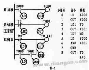
This is a ladder diagram (will not run). The vertical line on the left is called the left bus, and the right bus is not. The figure has three steps; the first step; the first contact on the left is normally open, the superscript is X000, X is the input relay, and the following 000 data can be considered as using the number in the input relay. The contact of the 000th (the same below). The correct representation of the instruction should be (as shown in the program on the right): 0, LD X000 (The first 0 is from the 0th step, the instruction input is ignored, it will automatically display in order).
The second step; the first contact on the left is a normally closed contact, the superscript is T0, T means the timer (different time length should be noted), 0 means the contact numbered 0 in the timer. The correct representation of its instructions should be: 2, LDI T0 (as shown in the program).
The third step; the first contact on the left is normally closed, the superscript is M0, M is the auxiliary relay (there are many kinds of relays, note category), the correct indication of the instruction should be: 4, LDI M0 (such as the program Show). The first contact of the second row of this step is normally open, and the superscript is Y000. Y represents the output relay. Since the contact is in series with the rear Y001 contact, a so-called circuit "block" is formed, so the touch The order of the point should be 5, LD Y000. In summary, the LD and LDI commands can be seen from the above, they are the instructions used by the first contact of each step of the left bus. The branch in the step (ie, the second row of the third step) has two or more contacts in series, and the first contact is also commanded by LD or LDI. The components that can use the LD and LDI commands are: input relay X, output relay Y, auxiliary relay M, timer T, counter C, and status relay S. OUT is the coil drive command, which cannot appear in the first position on the left bus. The drive coil and the drive coil cannot be connected in series, but can be connected in parallel. The same drive coil can only appear once and is placed at the last bit of each rung. As shown in the figure above, OUT Y000, 3, OUT Y001, Y are output relays. Once the coil receives the output signal, it can be considered that the coil will drive its corresponding contact and turn on the external load (the external load is mostly contact). , intermediate relays, etc.). In the above figure 8, OUT T0 K40 is the timer drive coil command, where K is the constant 40 is the set value (similar to the electrician's setting of the time relay). The OUT command elements can be used: output relay Y, auxiliary relay M, timer T, counter C, and status relay S.
(2) The series command of the contact AND (AND) ANI (and NOT); the former is normally open and the latter is normally closed. Both are used in series with a single contact. The two instructions can be repeated and are not restricted. As shown below.
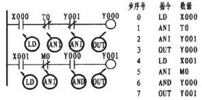
In the first step, the three contacts of X000, T0, and Y001 are in a series relationship, that is, the normally closed series of T0 is connected to the rear end of X000, and the normally closed of Y001 is connected in series with the rear end of T0 normally closed. Since they are normally closed, the ANI command is used. Now look at the second step; X000, M0, Y001, the same three contacts are also connected in series, the normally closed contact of M0 is connected in series with the back end of X001, and the normally open contact of Y000 is connected in series with the back end of M0. Therefore, the instruction of M0 uses ANI, and the instruction of Y000 uses AND (specifically, the above figure is detailed). In one sentence, if it is a series, it is normally open with AND, and if it is normally closed, it is ANI. The AND and ANI command elements can be used: input relay X, output relay Y, auxiliary relay M, timer T, counter C, and status relay S.
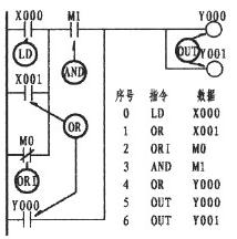
(3) Contact parallel command OR (or), ORI (or reverse); when the contacts are connected in parallel, regardless of several branches in the step, as long as the single contact is connected in parallel with the previous branch, it is normally open OR If it is normally closed, use ORI. As shown below.
In the first step, the three contacts of X000, T0, and Y001 are in a series relationship, that is, the normally closed series of T0 is connected to the rear end of X000, and the normally closed of Y001 is connected in series with the rear end of T0 normally closed. Since they are normally closed, the ANI command is used. Now look at the second step; X000, M0, Y001, the same three contacts are also connected in series, the normally closed contact of M0 is connected in series with the back end of X001, and the normally open contact of Y000 is connected in series with the back end of M0. Therefore, the instruction of M0 uses ANI, and the instruction of Y000 uses AND (specifically, the above figure is detailed). In one sentence, if it is a series, it is normally open with AND, and if it is normally closed, it is ANI. The AND and ANI command elements can be used: input relay X, output relay Y, auxiliary relay M, timer T, counter C, and status relay S.
It can be seen that the above figures X000, X001, M0 are in a parallel relationship. Since the two branches below X000 are single contacts, since X001 is a normally open contact, the OR command is used. While M0 is a normally closed contact, the ORI command is used. After the three contacts are connected in parallel, they are connected in series with M1. In series, they are connected in parallel with Y000. Y000 is also a single contact, so the OR command is still used. The OR and ORI command components can be used: input relay X, output relay Y, auxiliary relay M, timer T, counter C, and status relay S.
(4) Parallel command ORB (or) of the series circuit block; there are multiple (or single-branch) branches in any of the steps connected in parallel with the upper stage, as long as there are more than two contacts in the branch. (so-called: series circuit block), you should use the ORB instruction. As shown below.
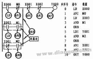
As can be seen from the above figure, the normally open contact of the first branch X003 is in series with the normally open contact of M1 (in this case, a block relationship is formed), which is in series with the X000 and M0 of the previous row. The latter phases are connected in parallel, and the program is written as shown in step numbers 0, 1, 2, 3, and 4. The first ORB that appears in 4 refers to the previous row. The second branch, normally closed Y001 and M2 are also in series. It is also a block structure, which is connected in series with the first branch. Therefore, the ORB appears again in step 7. The ORB instruction does not display ladder and data. It can be considered as such; it is a vertical line parallel to the previous line in the case where the next line forms a circuit block (two thick lines as shown in the figure).
(5) The serial command ANB between the parallel circuit block and the block; as shown in the lower left frame of the two circuit blocks, the circuit blocks are first combined and then the ANB instruction is used for the phase string. The ladder diagram on the left can be simplified with the image on the right. The program is written as shown below. The ANB command does not display ladder and data. It can be considered as such; it is a series connection relationship between the circuit block and the circuit block, and is a horizontal line. 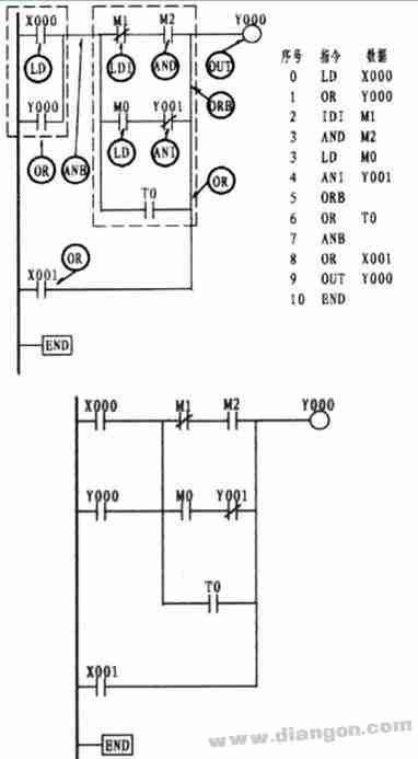
(6) Push instruction MPS, read stack instruction MRD, pop instruction MPP and program end instruction END; MPS, MRD, MPP This is a set of stack instructions. The two stack forms used in the following figure; MPS should be used in pairs with the MPP in stack form. As in the first stack form, the MPS and MPP instructions are used. If there is a branch in the middle of the MPS and MPP instructions, increase the MRD instruction as shown in the second stack in the figure below. It should be known that the number of MPS and MPP pairs should be less than 11 times, and the MRD instructions can be reused, but not more than 24 times. To know this set of instructions, there is also no display of ladder diagrams and data. It can be considered that MPS is the starting point of the stack, which acts as the connection point for the connection, and the MRD and MPP of the branch are connected in turn. The END instruction is the end instruction, which appears at the end of each program. 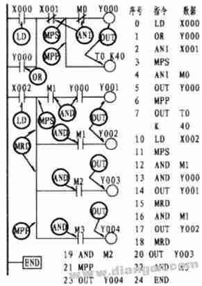
Of course, there are other instructions, but as long as I am familiar with the application of the above instructions, I thought that there should be no problem in entering the door, and it is enough. It is not difficult to study other instructions after entering the door. Therefore, no longer explain one by one.
4, familiar with the functions of the simple programmer's keys: The following is the FX-10P (handheld programmer) panel distribution (of course, less crystal display) and various key functions. The Chinese and component symbols marked under each key are added by me (the purpose is to find the object when inputting), and the rest are the same as the original keyboard (ie, the English and digital in the solid line). 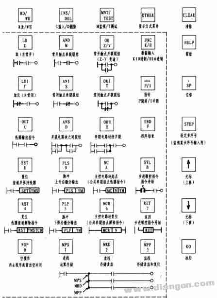
(1) Liquid crystal display; instructions (ie, instructions, component symbols, data) can be displayed during programming. The component working status can be displayed during the monitoring operation.
(2) keyboard; consists of 35 buttons, with function keys, command keys, component symbol keys and data keys, most of which can be switched. The keys work as follows:
1 function key: RD/WR... read/write, if R is the program readout in the lower left corner, if W appears, it will be written, ie W should appear when the program is input, otherwise the program cannot be input. . Press the first button as R, and press it again to press W. INS/DEL... Insert/Delete. If a program is missing during the program input process, press this button at this time, and I will enter the missing program. If you find that you have lost more than one program, press the same button to display D to delete redundant or incorrect programs. MNT/TEST...Monitoring/testing, T is testing, M is monitoring, and pressing this button can switch to each other. In the beginning, you should learn to use the monitor key M to monitor the running of the program to find out the problem and solve the problem.
2 Menu key: OTHER, Display mode menu 3 Clear key: CLEAR, press this key to clear the currently entered data.
4 Help key: HELP, display application command list, in the monitoring mode, decimal and hexadecimal numbers are converted.
5-step key: STEP, monitor the input step number of a step.
6 Spacebar: , / SP, used to specify the component number and constant when inputting an instruction.
7 Cursor keys: ↑, ↓, use these two keys to move the cursor on the LCD screen to scroll (up or down).
8 Execution key: GO, this key is used to input the confirmation, insertion, deletion execution of the instruction, and so on.
9 command key / component symbol key / number key (in the dotted line): These keys can be automatically switched, the upper part is the command key, and the lower part is the component symbol key or number key. Once the command button is pressed, the other keys are switched to the component symbol or number, and the selection input can be made. Other Z/V, K/H, and P/I can be switched to each other with the same key.
5, familiar with the operation of the programmer to connect the PLC and the simple programmer as specified. The PLC is powered on and the small indicator light is on. Turn the twist switch on the PLC to the STOP position.
Operation point 1 clear: When the twist switch is turned to the STOP position, English will appear, leave it alone. Press RD/WD directly (so that W is written on the left side of the display). At this time, press NOP, then press A in MC/A, and then press the second GO to confirm (ie: W→NOP→ A→GO→GO).
2 Input command: If the command LD X000, input LD→X→0→GO in the following order, the LD X000 will be displayed automatically on the screen. Other instructions are analogous. For ORB, ANB, MPS, MRD, MPP, END, NOP and other instructions, just press GO to confirm (ORB→GO) after input.
3 Timer input: If the command OUT T0 K 40 is input in the following order, OUT→T→0→, /SP→K→40→GO (T0 is 100ms, the setting value is: 100×40=4000ms =4S).
4 Delete command: Move the cursor to the command to be deleted, set the INS/DEL button to D, and then confirm with GO. That is: move the cursor to the command to delete → D → GO.
5 Insertion command: If you want to insert a new step between steps 4 and 5, move the cursor to 5, set the INS/DEL key to I, confirm it, and then enter the new program to confirm again. To insert AND Y001, move the cursor to the part to be inserted → I → GO → AND → Y → 1 → GO.
6GO key: Enter the GO to confirm each step input.
7 End command: After each program input is completed, the END command should be input at the end to run the program.
8 After the input command is completed, the twist switch on the PLC should be turned to RUN in the running state. If there is an audio or a light, there is a problem with the input program.
6. Input simple runnable program to run in the monitoring state: Learn to use the monitor key M at the beginning of the school, you can monitor the running status of the program from the LCD display, and deepen the understanding of the PLC contact operation. And it is the best way to find out the problem and solve the problem.
The specific operation is as follows: Press the MNT/TEST button to place the M monitor operation mode, and move the cursor to check the operation of the entire program. If the â– mark appears in the program, the component is in the ON state (ON), and if there is no â– mark, the component is in the OFF state (OFF).
7. Try to draw a simple ladder diagram: the editing of the simple ladder diagram, generally based on the existing electrical schematic diagram, according to its working principle, draw from shallow to deep, first seek to draw, then seek simple and clear, and slowly understand Draw a ladder diagram. First of all, we must understand the working principle of the electrical schematic, according to the working principle of the electrical schematic, and then draw according to the requirements of the PLC. It should be grasped that it is not possible to simply associate the PLC contacts with the contacts on the electrical schematic (this is a common problem for beginners). If this is the case, it is possible to step into a dead end, and the ladder diagram drawn can achieve the purpose. Just fine.
1 irreversible start to use PLC control 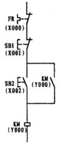
figure 1 
figure 2
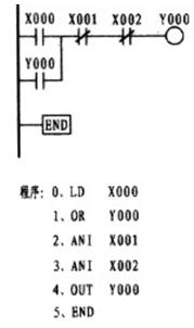
image 3
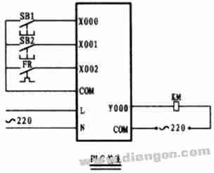
Figure 4
Figure 1 of the above figure is an electrical schematic diagram, and Figure 2 is a ladder diagram drawn according to the principle of one-to-one correspondence with the schematic diagram. Its characteristics are easy to understand, but few of my impressions can be drawn like this. If you draw in this way, you will likely go into no return. Although both figures can be run, if Figure 2 is changed to become Figure 3, it can be seen that Figure 3 has one step ANB missing from the program. Concise and clear is the element of programming. Therefore, when programming the ladder diagram, the multi-contact parallel contacts should be placed on the side of the busbar of the ladder diagram as much as possible to reduce the ANB instruction. X000 in Figure 2 and X002 in Figure 3 are normally closed contacts controlled by an external thermal relay, while thermal relays use normally open contacts (or the normally closed contacts of external thermal relays can also be connected to contactor coils). In series). Only after drawing the ladder diagram, the program is programmed according to the ladder diagram.
Working principle: Take Figure 3 as an example. When the external start button is pressed, the normally open contact of X000 immediately closes the current (actually energy flow), and flows through the normally closed contact of X001 and X002 until the output relay Y000 is closed, because Y000 The closing of the Y000 normally open contact connected to the busbar side forms a self-protection, and the external contactor is turned on by the output relay, thereby controlling the operation of the motor. When the external stop button is pressed during the stop, the X001 normally closed contact is instantaneously interrupted, and the output relay coil is turned off, and the external contactor stops. When the motor is overloaded, the external thermal relay normally closes the contact point and leads to the X002 normally closed contact to open, thus protecting the motor.
2 start, jog control to use PLC control 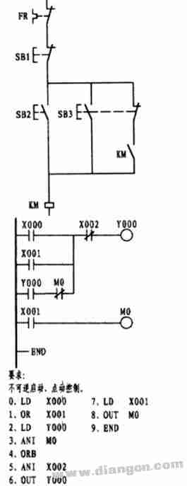
This question is often a hurdle for beginners. This is mainly because the relay electrical schematic uses a composite button, resulting in a mindset. It can be seen from the ladder diagram that X001 is a jog control contact. Because the electric schematic on the left is a composite button used, the thinking naturally turns to the normally closed contact with X001, which forms and recombines with the normally open of X001. The similar effect of the button, the imagination is good. To know that the PLC is in the running state, it is scanned in the order of scanning, and one scan is executed, and the scanning speed is extremely fast. If the normally closed of X001 is used instead of the normally closed M0, when the external jog button is pressed, the X001 normally open contact is closed and the normally closed contact is closed, but once the normally closed contact is released, the normally closed contact is almost closed. Self-protection, so lost the jog function, become a function that only starts. The second branch of the first step in the ladder diagram is formed by the normally open phase of Y000 and the normally closed phase of the intermediate relay M0, and then with the first branch. If there are many contacts, if it is allowed, It is placed on the first line, so you can use less ORB instructions when programming.
AC (Alternating Current) Power cord is to transmit high voltage. It is used to drive machinery or home appliances. Since AC Power Cord is output of high voltage electric power, there is a risk of electric shock injury, therefore, All the AC power cord must comply with safety standard to produce. DC (direct Current) power cord is used to the applicance with lower voltage mostly, so safety requirement is less stringent.
Power Cable, battery cable, DC power cable, AC power cable, power cord
ETOP WIREHARNESS LIMITED , https://www.oemmoldedcables.com