The lighting switch is installed on the entrance and exit of the corridor. At night, when a pedestrian enters or exits from the entrance of the corridor, the light will turn off automatically after being turned on for a period of time. During the day, the lights automatically stop working.
(I) Working principle The main component of the sensor switch is a new pyroelectric infrared detection module HN911L and a V-MOS tube.
The HN911L internal circuit includes high-sensitivity infrared sensors, amplifiers, signal processing circuits, and output circuits. The pyroelectric infrared sensor telemeters the micro-thermal infrared signal emitted by the moving human body and sends it to the HN911L to obtain the amplified electrical signal at the output end.
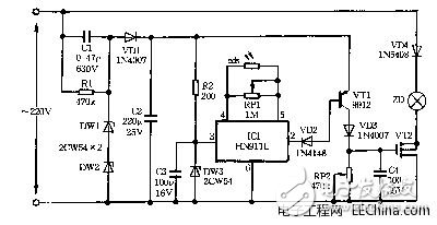
The input impedance of the V-MOS FET is extremely high. After the capacitor between the gate and source is charged, the capacitor voltage can be maintained for a long time. During this period, the V-MOS transistor is turned on. With this feature, delay functions can be implemented. The circuit principle of this switch is shown in Figure 2.5.1. 220V mains voltage is obtained by C1 step-down, VDl rectification, DWl, DW2 voltage regulation, C2 filtering to get 12V DC voltage. This voltage in addition to the transistor VTl power supply, after the R2 step-down, DW3 regulator, C3 filter to get 6V voltage for ICl power. When ICl does not detect the infrared signal, the output pin 2 is high. VTl does not have base bias and cuts off, VT2 also cuts off, the bulb ZD does not shine. When someone enters the entrance of the corridor, infrared rays emitted by the moving human body are received by the infrared sensor. After being processed by the ICl, the pin 2 outputs a low level and the VTl is turned on. 12V DC voltage is charged to capacitor C4 by VTl, VD3, VT2 rapidly saturates and turns on, bulb ZD is bright. After the person walks, the ICl2 foot returns to the high level, and VTl ends. At this time, VT2 continues to conduct during C4 discharge. As the voltage on C4 goes down, VT2 goes from the saturation zone to the zoom-in zone until the cut-off zone, and ZD also gradually dims from light to extinct. In the circuit, RPl is the gain adjustment resistance of ICl, RP2 is the lighting delay time adjustment potentiometer. The cds is a photoresistor, which is illuminated by light during the day and has a very low resistance, so that the ICl gain is extremely low, and the output of the 2nd pin is not. At night, the cds have a large resistance, and the IC1 resumes its work. The cds can be exposed to light, because once VT2 is turned on, even if VTl is turned off immediately, VT2 can still be operated by C4 discharge.
(b) Component Selection
1. ICl uses a new pyroelectric infrared detection module HN911L.
2. VTl selects model 9012 triode; V12 selects BV ≥500V, 3A V-MOS tube, such as BUZ358 and so on.
3. DVl, VD3 use 1N4007 diode; VD2 selects 1N4148 diode; VD4 selects 1N5408 diode;
DWl-DW3 selects model 2CW54 Zener diode.
4. Other components are marked as shown in the figure, no special requirements.
(III) Production and Debugging According to the size of ICl, open an appropriate size hole on the non-porous switch cover, place the sensor surface of the ICl facing outwards, flush with the outer surface of the cover plate, and stick it with 502 glue. The rest of the components are soldered to a circuit board and connected to the ICl using a soft wire. The photo-resistor is preferably mounted in the same way as ICl to receive light and the entire device is placed in the switch box. Since the human body is in close proximity to the infrared sensor switch when entering or leaving the corridor, the switch can generally work reliably. To increase the detection distance, a corresponding Fresnel lens can be attached to the front of the sensor. When debugging, first disconnect the photoresistor, adjust RPl, and let the light bulb light up when passing by the sensor. Then solder the photoresistor, cover the light and fine tune it again. Then adjust the RP2 so that the lamp light time is appropriate.
Liquid Crystal Display Monitor is a Liquid Crystal Display with a monitoring BNC signal processing terminal using a 7*24 hour professional power module and a monitoring driver scheme using Liquid Crystal Display technology.
size
LCD screen size refers to the LCD display part of the diagonal length. 1 inch =2.56 cm. In order to make a whole LCD screen produce the highest profit after cutting, a lot of research has been done on cutting technology. Take the LCD screen used by the 20-inch LCD monitor, there are 19.7-inch LCD screen and 20.1-inch LCD screen. But we generally call it a 20-inch liquid crystal.
The power supply board
Liquid crystal monitor and common liquid crystal display and liquid crystal TV all need to use liquid crystal power board to supply the liquid crystal screen. The difference lies in the choice of power board, general LCD monitor will use 7*24 hours of industrial power board; And because the market that monitor and liquid crystal TV are aimed at itself basically is civil market, the power supply that USES basically still is common power supply.
clarity
Similar to contrast, these two parameters are also important indicators to evaluate the effect of an LCD monitor. In theory, the higher the clarity, the better the picture.
Open Frame Lcd Kit,Open Frame Lcd Display,Elo Open Frame Touch Screen Mo,19 Inch Open Frame Monitor
Shenzhen Zhenniu Technology Co., Ltd , https://www.tydisplay.com