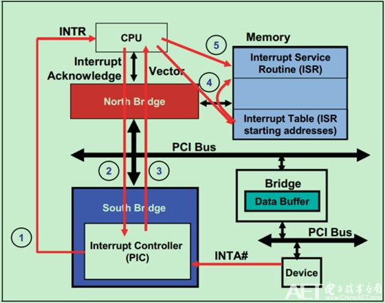
A simple PCI bus INTx interrupt implementation process is shown in the figure below.
1. First, the PCI device generates an interrupt request through the INTx sideband signal. After passing through the Interrupt Controller (PIC), it is converted to an INTR signal and sent directly to the CPU;
2. After the CPU received the INTR signal set, it realized the interrupt request occurred, but at this time it did not know what the interrupt request was. Therefore, a special instruction is used to query the interrupt request information. This process is generally called Interrupt Acknowledge;
3. After the special instruction is sent to the PIC, the PIC will return an 8bits Interrupt Vector value to the CPU. The interrupt vector value corresponds to the INTR request sent;
4. After the CPU receives the interrupt vector value from the PIC, it will go to the Interrupt Table (Interrupt Table) in the Memory to find the location of the corresponding Interrupt Service Routines (ISR) in the Memory;
5. Then the CPU reads the ISR program, and then processes the interrupt.

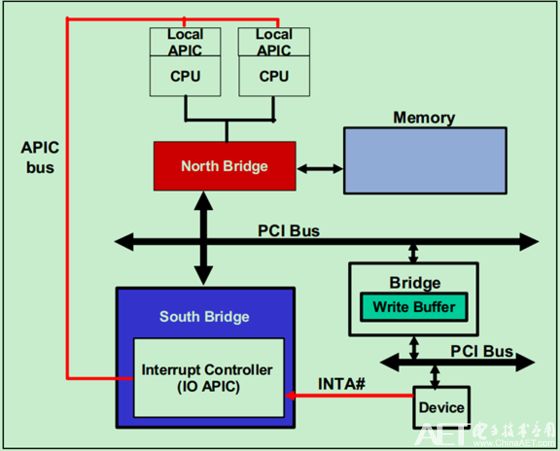
The above example is mainly based on the early single-core CPU design, and does not take into account the current multi-core CPU. Therefore, in the subsequent PCI Spec, PIC is replaced with IO APIC (Advanced Programmed Interrupt Controller). As shown below:
In fact, in the PCIe bus, the traditional interrupt mechanism (INTx) is rarely used, and many applications even directly disable this function. Whether in the PCI bus (V2.3 and later) or PCIe bus, you can disable the INTx interrupt mechanism through the configuration command register (Configuration Command Register) in the configuration space, as shown in the following figure. However, it is important to note that although the name of this bit is Interrupt Disable, it will only affect INTx and will not affect MSI/MSI-X. Because the enabling (or disabling) of MSI/MSI-X is achieved through the MSI/MSI-X Capability Command Register in the configuration space, and once MSI/MSI-X is enabled, the PCI bus/PCIe bus will automatically INTx is prohibited locally.
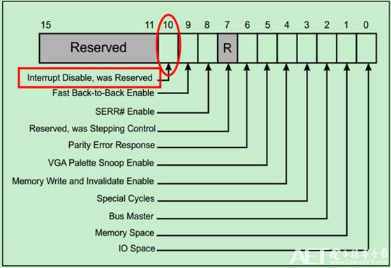
And you can determine the current interrupt status by configuring the Interrupt Status bit of the status register, as shown in the following figure:

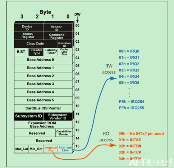
The location of INTx-related registers in the configuration space is shown in the figure below. Interrupt Pin and Interrupt Line respectively define the interrupt sideband signal pin number (INTA#~INTD#) and interrupt vector number (IRQ0~IRQ255).
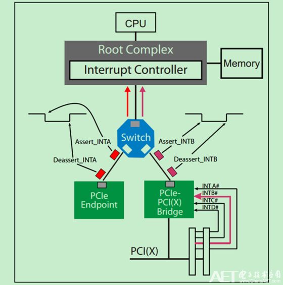
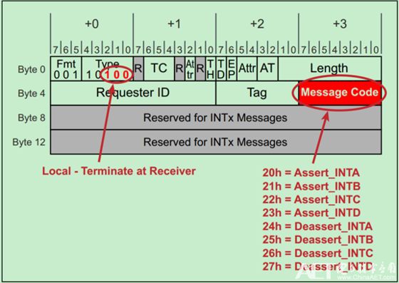
However, the PCIe bus inherits the INTx interrupt mechanism of the PCI bus, but the sideband signal INTx is not used in the actual transmission of interrupt information between PCIe devices, but based on messages. The Assert_INTx message represents the falling edge of the INTx signal. The Dessert_INTx message represents the rising edge of the INTx signal. When sending these two messages, the PCIe device will also update the value of the relevant interrupt status bit in the configuration space. For PCIe-PCI (X) bridge devices, the received INTx signal from the PCI/PCI-X bus is converted into a message and sent to the upper level. A simple example is shown in the figure below:
The format of the INTx message is:
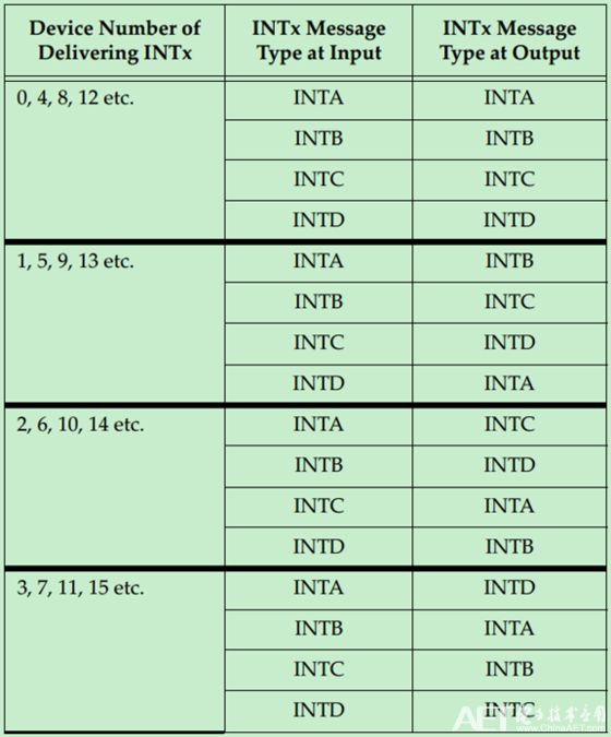
The mapping relationship between the type of INTx message in the bridge device and the device number is shown in the following figure:
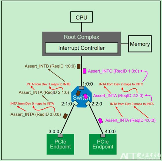
Correspondingly, a simple example is as follows:
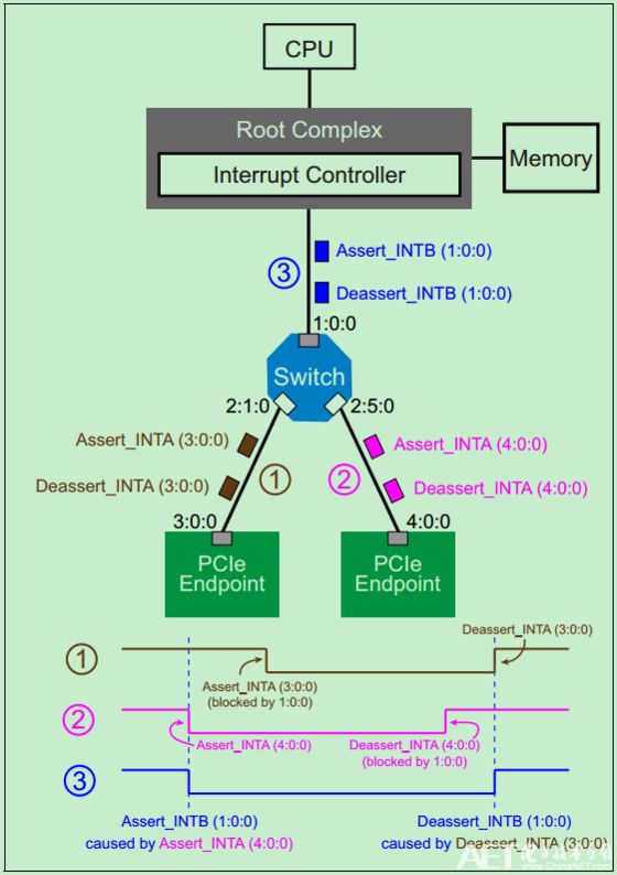
When multiple devices use the same interrupt signal line, only the device that is set first will be responded by the interrupt controller. However, the interrupt signal line will not be cleared because the interrupt request of one of the devices is responded, but will wait until the interrupt request of all the requesting devices have been responded. As shown below:
everyone enjoys luck , https://www.eeluckwatch.com