The inverter is also called the power regulator. According to the use of the inverter in the photovoltaic power generation system, it can be divided into two types: independent power supply and grid connection. According to the waveform modulation method, it can be further divided into a square wave inverter, a staircase wave inverter, a sine wave inverter and a combined three-phase inverter. For the inverter used in the grid-connected system, it can be divided into a transformer type inverter and a transformerless type inverter according to the presence or absence of a transformer.
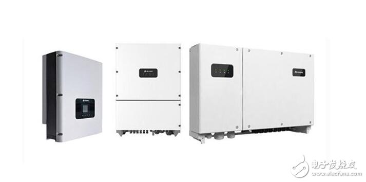
Generally, the process of converting AC power into DC power is called rectification, the circuit that completes the rectification function is called a rectification circuit, and the device that implements the rectification process is called a rectification device or a rectifier. Correspondingly, the process of converting DC power into AC power is called inverter, and the circuit that completes the inverter function is called an inverter circuit, and the device that implements the inverter process is called an inverter device or an inverter. As mentioned above, there are many types of inverters, so special care must be taken when selecting the model and capacity. Especially in solar power systems, the efficiency of the inverter is an important factor in determining the capacity of the solar cell and the size of the battery. .
Photovoltaic inverter working principle
The inverter is a power adjustment device composed of a semiconductor device and is mainly used for converting direct current power into alternating current power. It is generally composed of a booster loop and an inverter bridge loop. The boost circuit boosts the DC voltage of the solar cell to the DC voltage required for inverter output control; the inverter bridge circuit converts the boosted DC voltage equivalently to the AC voltage of the common frequency. The inverter is mainly composed of switching elements such as transistors, and the DC input is made to be an AC output by regularly turning the switching elements on and off (ON-OFF). Of course, it is not practical to simply output the inverter output waveform from the open and closed loops. Generally, high-frequency pulse width modulation (SPWM) is required to narrow the voltage width near the sine wave, and the voltage width at the center of the sine wave is widened, and the switching element is always moved in one direction at a certain frequency in a half cycle, thus forming A pulse wave train (quasi-sine wave). Then let the pulse wave form a sine wave through a simple filter.
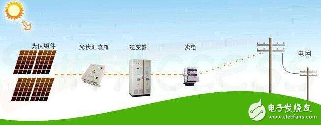
1, current sensor
Photovoltaic inverters generally use Hall current sensors for current sampling. The current sensors used from low power to high power are of different forms. Some examples are as follows:
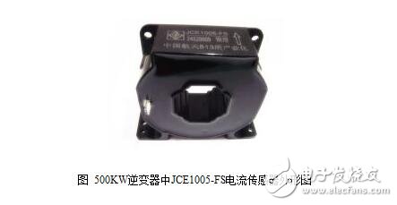
100KW: The detection current is about 300A, and the JCE308-TS7 current sensor is generally used.
250KW: The detection current is about 500A, and the JCE508-TS6 current sensor is generally used.
500KW: The detection current is about 1000A, and the JCE1005-FS current sensor is generally used.
1MW: The detection current is about 2000A, and the JCE2005-FS current sensor is generally used.
For current sensors, high precision, fast response time, and low temperature, high temperature and other environmental requirements
2, current transformer
Generally, BRS series current transformers are used, ranging from several hundred to several thousand A. The output signals are generally 0-5A.
3, reactor
There are many different classification methods for PV inverters. According to different applications, it can be divided into independent power supply inverters and independent grid-connected inverters (depending on the presence or absence of transformers, independent grid-connected inverters) It can also be divided into transformer type inverters and transformerless type inverters). According to the different waveform modulation methods, it can be divided into square wave inverter, ladder inverter, sine wave inverter and combined three-phase inverter.
Square wave inverter
The voltage waveform output by the inverter is a square wave, the inverter circuit is simple, the price is cheap, and the implementation is relatively easy. The disadvantage is that the square wave voltage contains a large amount of higher harmonic components, which will cause additional losses in the load and cause large interference to devices such as communication, and additional filters are required. Such inverters are more common in the early days, designing small-capacity inverters with powers not exceeding several hundred watts.
2. Step wave inverter
The voltage waveform outputted by the staircase wave inverter is a stepped waveform. The advantage of the staircase wave inverter is that the output waveform is close to a sine wave, which is significantly improved compared to the square wave, and the higher harmonic content is reduced. When the step of the step wave reaches more than 16 f, the output waveform is a quasi-sine wave, and the overall efficiency is high. However, the inverter often needs multiple sets of DC power supply, and more power switch tubes are required, which brings inconvenience to the photovoltaic array grouping and battery grouping.
3. Sine wave PWM inverter
The advantage of the sine wave inverter is that the output waveform is basically a sine wave, and there is only a small amount of harmonic loss in the load, which has little interference to the communication device and high efficiency of the whole machine. The disadvantage is that the equipment is complicated and the price is high. With the advancement of power electronics technology and the popularity of pulse width modulation technology, large-capacity PWM type sine wave inverters have gradually become the mainstream products of inverters. Taking a typical single-phase full-bridge inverter as an example, four diagonal switching power tubes are grouped by two switching tubes of each diagonal, which are sequentially turned on and off, and are generated at the two ends of the load. Alternating positive and negative voltages form an AC output. When the frequency of this alternate conduction is the same as the AC frequency required by the load, the output voltage is the square wave voltage. When the switch tube is switched at a frequency much higher than the inverter AC output voltage, and the pulse width of each switch is modulated according to the amplitude of the sine wave, it becomes an inverter with a sine wave pulse width modulation output, and a filter is added. After that, the output voltage waveform is a sine wave output inverter.
PWM type inverters widely use power MOSFETs, insulated gate bipolar transistors
(IGBT), turn-off thyristor (GTO), etc. are used as switching transistors, while the control part uses a dedicated PWM switching integrated circuit and a DSP and a microcontroller chip with a PWM output. The construction of a practical inverter requires a main power circuit, a control circuit, and an auxiliary circuit (such as protection, measurement, and monitoring). The inverter process is: the DC output of the photovoltaic array or the battery enters the DC bus of the inverter, and the DC pulse is converted into a sinusoidal modulated AC pulse wave by a switching circuit (such as a bridge circuit). The pulse-width-modulated AC voltage is converted into a sinusoidal AC voltage output through a filter circuit. If a boost is required, an external step-up transformer is connected, and the AC power is sent to the load via the transmission line. The frequency of the PWM modulated output signal is called the modulation frequency or switching frequency of the inverter. It is generally ten times, several tens to hundreds of times the frequency of the fundamental frequency of the inverter output. The typical inverter AC output frequency is 50Hz, and the inverter switching frequency can be as high as ten to ten kilohertz. The higher the switching frequency of the PWM modulation, the smaller the harmonic of the output waveform of the inverter, but the greater the power loss caused by the switching process, the tradeoff of the PWM modulation of the switching transistor is to be weighed.
The filter connected to the inverter output is usually a low-pass filter, and the inductor and capacitor form a T-type low-pass filter. The design of the filter should consider the filtering ability as well as the possible electromagnetic resonance. The inverter is divided into a voltage type inverter and a current type inverter according to the output type.
4. Transformer
The frequency converter is composed of a three-phase rectifier, a passive inverter of a voltage source and a controller. Since the power generated by the photovoltaic power generation system is DC specific, the photovoltaic frequency converter does not need a three-phase rectifier, but directly directs the direct current of the frequency converter. The busbar is connected to the DC bus of the photovoltaic system. In view of the fact that the photovoltaic power is greatly affected by the natural environment of the light, the DC bus generally needs to add a battery to stabilize the operation of the inverter; the weak control signal should be added to the control terminal of the inverter, the set frequency of the inverter is constantly adjusted, and the inverter is changed. Output power to achieve the goal of tracking with the maximum power point of the PV array. As an adjustable load, the frequency converter should be controlled jointly with the MPPT of the photovoltaic array. In the photovoltaic power generation system, the motor type dynamic load should be used as much as possible to reduce the impact of the motor starting current, and the motor load can be flexibly adjusted.
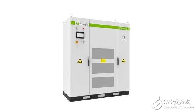
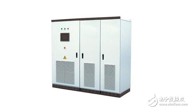
As an important part of photovoltaic power generation, the main function of the inverter is to convert the direct current generated by the photovoltaic module into alternating current. At present, the common inverters on the market are mainly divided into centralized inverters and string inverters, as well as trendy distributed inverters.
1. Centralized inverter
As the name suggests, centralized inverters convert the DC power generated by PV modules into AC power, and then boost and connect to the grid. Therefore, the power of the inverter is relatively large. A centralized inverter of more than 500 kW is generally used in photovoltaic power plants.
The advantages of a centralized inverter are as follows:
(1) High power, small quantity, easy to manage; few components, good stability, easy to maintain;
(2) Low harmonic content, high power quality; complete protection function and high safety;
(3) There are power factor adjustment function and low voltage ride-through function, and the power grid is well regulated.
The centralized inverter has the following problems:
(1) The centralized inverter MPPT voltage range is narrow, and it is impossible to monitor the operation of each component. Therefore, it is impossible to make each component at the optimal working point, and the component configuration is not flexible;
(2) The centralized inverter has a large area and requires a dedicated machine room, and the installation is not flexible;
(3) The power consumption of the self and the ventilation and heat dissipation of the equipment room consume a large amount of electricity.
2, string inverter
As the name suggests, string inverters convert DC power generated by PV modules directly into AC power, boost, and grid. Therefore, the power of the inverter is relatively small. In the photovoltaic power station, a string inverter of 50 kW or less is generally used.
String inverter advantages:
(1) It is not affected by the difference between the modules of the string and the shadow occlusion, and at the same time, the optimal working point of the photovoltaic cell module is not matched with the inverter, and the power generation is maximized;
(2) The MPPT voltage range is wide, and the component configuration is more flexible; in the rainy days, the foggy area is more, and the power generation time is longer;
(3) Small size, small footprint, no need for a dedicated machine room, flexible installation;
(4) Low self-consumption and low impact.
There is a problem with the string inverter:
(1) The power device has small electrical clearance and is not suitable for high altitude areas; there are many components, integrated, and the stability is slightly poor;
(2) Outdoor installation, wind and sun exposure can easily lead to aging of the outer casing and heat sink;
(3) The number of inverters is large, the total failure rate will increase, and the system monitoring is difficult;
(4) Without isolation transformer design, electrical safety is slightly poor, and it is not suitable for negative electrode grounding system of thin film components.
3. Distributed inverter
The distributed inverter is a new inverter form proposed in the past two years. Its main features are “centralized inverter†and “distributed MPPT trackingâ€. The distributed inverter is a product that combines the advantages of both the centralized inverter and the string inverter. It achieves the low cost of the centralized inverter and the high power generation of the string inverter. ".
Distributed inverter advantages:
(1) Compared with centralized, “distributed MPPT tracking†reduces the probability of mismatch and increases the amount of power generation;
(2) Compared with the centralized and string type, the distributed inverter has a boost function, which reduces the line loss;
(3) Compared with the string type, “centralized inverter†has more advantages in terms of construction cost.
Distributed inverter problem;
(1) Less engineering experience. Compared with the first two categories, it is still a new form and has relatively few applications in engineering projects;
(2) The characteristics of safety, stability and high power generation also need to go through the inspection of engineering projects;
(3) Because of the “centralized inverterâ€, the large area and the disadvantages of the dedicated equipment room also exist in the distributed inverter.
There are a few different types of slip rings, but the most common type is called a cap slip ring. Cap slip rings have a cylindrical housing with an internal flange that fits over the end of the shaft. They typically have 6 or 12 channels and are available in a wide range of sizes.
Cap slip rings are used to provide electrical power and signals to and from rotating equipment. The channels on the slip ring allow for the passage of current and/or data signals through the ring. This allows for the rotation of devices such as antennae, radar dishes, and wind turbines without having to interrupt or disconnect the power or signal lines.
Cap slip rings are very reliable and can handle high speeds and heavy loads. They are also easy to install and maintain.
In the modern world, companies are always looking for ways to improve the efficiency of their machines and operations. Oubaibo offers a variety of products that can help improve your machine's performance. Their Cap Slip Ring allows for high-speed rotary unions, while their high-pressure swivel joints can handle even the most strenuous industrial applications. With so many options available, there's sure to be an Oubaibo product that can improve your machine's performance.
Cap Slip Ring,High Speed Rotary Unions,High Pressure Swivel Joints,High Pressure Swivel Joint
Dongguan Oubaibo Technology Co., Ltd. , https://www.sliproubos.com