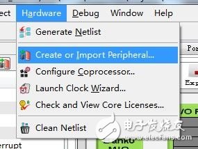
If you want to take advantage of the ZYNQ chip and let the whole system work together, you need to combine the PS and PL parts to establish a communication channel between the Cortex-A9 core and the FPGA logic resources. This channel is the AXI bus. ZedBoard's official example has already introduced how to add Xilinx's AXI bus IP (such as AXI_TImer, AXI_GPIO, etc.) to the project, so let's write a simple AXI bus device - read board 8 SwTIch states on the top and control 8 LED switches. Some people will ask me if I don't understand the AXI bus. I don't have to worry about it. Xilinx has designed a setup wizard for us to automatically generate a device template. Even if you don't understand the AXI protocol, you can easily complete the design work. First create a system project through PlanAhead and import the ZedBoard xml file: zedboard_RevC_v2.xml. For children whose shoes are still unclear, please download the ZedBoard_CTT_v14.1 information on the ZedBoard website and follow the document for literacy. This information is very detailed and is also Step By Step, which can help to complete basic operations and learning. After the project is built, enter the XPS interface and select Hardware→Create or Import Peripheral to start creating the peripherals. (If you can't see the picture, you can click on the small picture to enlarge, the same below)
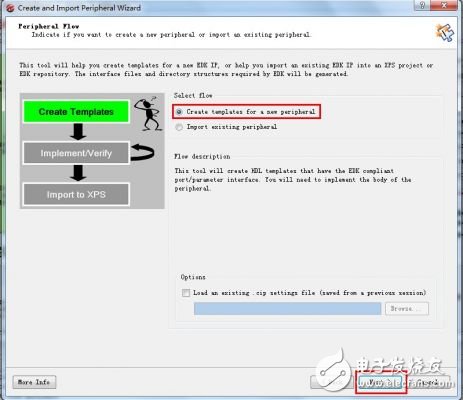
In the pop-up window, select New Template to create a peripheral.
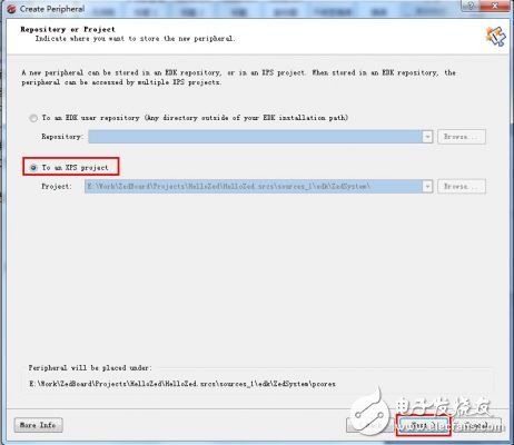
Next, select to integrate into the XPS system, so the newly created peripherals will be saved in the pcores folder under the edk directory.
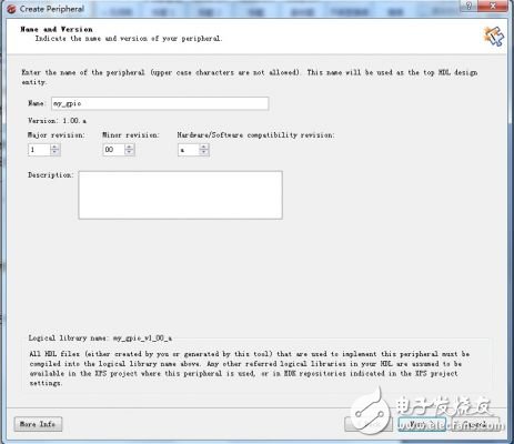
Next, Next, give your IP a name, called my_gpio, the full name is my_gpio_v1_00_a, and note that the name cannot be capitalized.
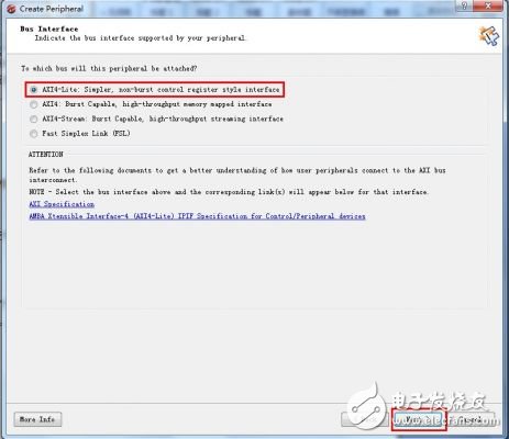
After selecting the type of bus, it can be seen that there are several variants of AXI bus devices, which can make the device capable of burst operation and large amount of data transmission. Here we choose AXI4-Lite form, which is the simplest type.
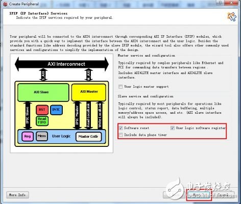
The next step is to configure several options, including software reset, master-slave mode, etc. Check the two items, although no software reset is available.
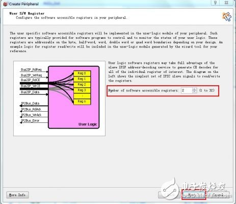
Set the number of registers, here we set two 32-bit registers (actually using the lower 8 bits, the other part is Not Care), one for controlling the LED and the other for reading the SW state.
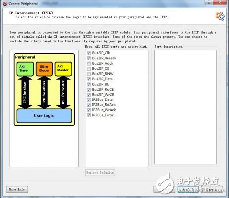
Select the required IP connection signals. These are the signals that are connected to the user logic and remain the default.
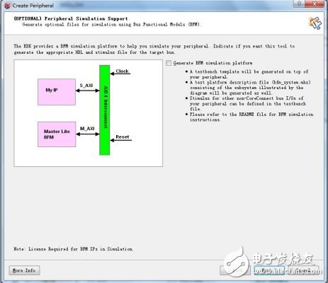
This step can be used to build a simulation device on the bus, no need to go directly to Next.
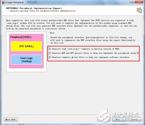
To the other configuration screen, the first option is to use Verilog to design the user logic; the second option to create an ISE project file, write code; the third option allows XPS to automatically generate the underlying control code.
After the setting is finished, you can find the IP folder in the XPS project directory. The path for the rabbit here is ".\Hello_Zed.srcs\sources_1\edk\module_1\pcores\my_gpio_v1_00_a". There are three folders inside, and the hdl folder contains user_logic.v and my_gpio.vhd. The former is the user logic file we want to modify, and the latter is the VHDL file used to connect AXI with user logic and encapsulate the IP core. This file can only be VHDL, so it is very boring like Verilog like a rabbit. Fortunately, the content inside is very simple. You can understand it by looking at it. In the devl\projnav folder you can find the newly generated ISE project, open my_gpio.xise with Project Navigator, and you can start editing user_logic.
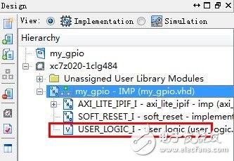
In addition to some definitions and signal connections, user_logic is two always blocks. The first one implements the AXI bus to write data to the user register, and the second is the bus reads data from the register. It should be noted that the AXI bus here has been transferred through Xilinx's AXI Lite IP Interface, which becomes a very simple read and write logic to the user. In order to control the hardware on the board, we define two sets of signals and corresponding registers: SW_In signal is connected to 8 switches, and LED_Out is connected to 8 LEDs. input [7: 0] SW_In; output [7: 0] LED_Out; where 0 is a predetermined register SwTIch status register, register 1 is an LED control register. Add an always block so that the data written to register 1 is updated on LED_Out. always @ (posedge Bus2IP_Clk) begin if (Bus2IP_Resetn == 1'b0) begin LED_Out <= 0; end else begin LED_Out [7: 0] <= slv_reg1 [7: 0]; end end // LED_OUTPUT_PROC simultaneously added so Switch logic The state is written to register 0 by simple synchronization (not debounce). // implement slave model register read mux always @ (slv_reg_read_sel or slv_reg0 or slv_reg1) begin case (slv_reg_read_sel) 2'b10: slv_ip2bus_data <= slv_reg0; 2'b01: slv_ip2bus_data <= slv_reg1; default: slv_ip2bus_data <= 0; endcase end / / SLAVE_REG_READ_PROC always @ (posedge Bus2IP_Clk) begin if (Bus2IP_Resetn == 1'b0) begin SW_Reg0 <= 0; SW_Reg1 <= 0; slv_reg0 <= 0; end else begin SW_Reg0 <= SW_In; SW_Reg1 <= SW_Reg0; slv_reg0 [7 : 0] <= SW_Reg1 [7: 0]; end end modification even after the read and write logic // SWTICH_INPUT_PROC, comment out the entry at the 2'b10 case (slv_reg_write_sel), read-only instruction register 0 (data write Not Care), register 1 can be read and written. So, our user logic is complete, simple. Don't forget to add ports to user logic in my_gpio.vhd. The two sets of signals are named GPIO_LED_Out and GPIO_SW_In in the external interface of the entire IP.

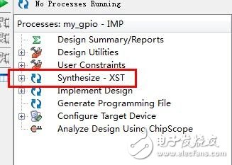
The specific code content is here: my_gpio_hdl.rarDouble -click on Synthesize and check if there are any problems. If you have no problem, you can turn off Project Navigatorl.
Back to the XPS interface, our custom IP is already in the list, but at this time the IP is added to the project, the editing just done does not take effect, the GPIO port is not displayed in the IP core block diagram, this rabbit does not Understand why it is possible to manually modify the MPD file. So I chose to add this IP again (unfortunately, there are any good ways to enlighten me), or just the method, but this time choose to import existing peripherals, this method can also be used to import other Existing IP core.
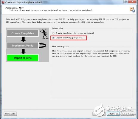
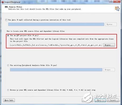
Still named my_gpio, select Yes to overwrite the pop-up prompt, then all the way to the HDL Source Files window, select the \data\_my_gpio_xst.prj file of the IP core.
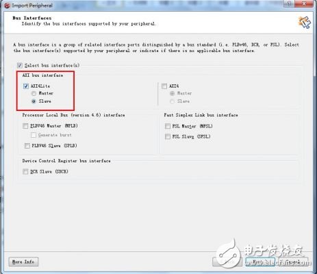
Continue to Next until the bus type is selected as AXI4-Lite Slave type.
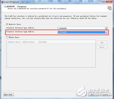
Then specify the parameter of High Address in the parameter window as C_HIGHADDR.
Ok, Next to the end, the changes you just made have taken effect and have been successfully imported. Now double-click my_gpio to keep the default options and add them to the system.
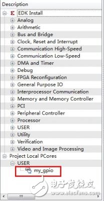
In the Graphic view, you can see the block diagram of my_gpio, including a set of connected AXI buses, and the two sets of ports we just defined.

Enter the Port interface and set the LED and SW ports to external, making sure that this looks like this.

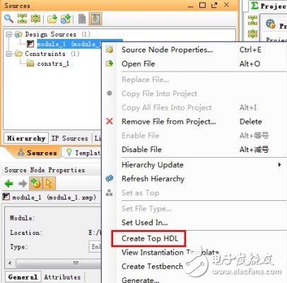
Ok, turn off XPS, go back to PlanAhead, and generate Top HDL (if you did it before you can ignore it).
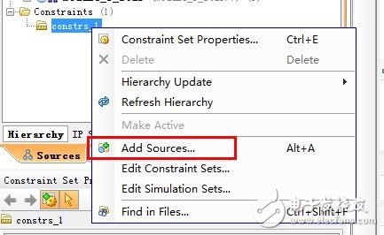
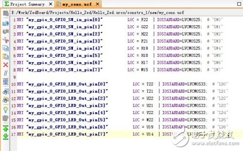
Create a new constraint file and set the port constraints for SW and LED.
The content of the constraint is as follows (recommended manual input, if copying illegal characters is very troublesome, it hurts me to check for a long time):
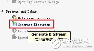
Select Generate Bitstream, the system will automatically complete the compilation and synthesis work, and finally generate a System.bit file containing PL configuration information.
At this point, the my_gpio custom peripheral is complete, this PL can now communicate with the PS via the AXI bus - let's still need software support, huh, huh. The next section will show you how to debug peripherals with bare metal software. The steps are similar to those in the ZedBoard_CTT documentation. the above.
RCM Temperature Detector
Electrical fire monitoring detector is mainly used for residual current alarm measurement, temperature monitoring, three-phase power grid electricity measurement, harmonic measurement, electric energy measurement and other functions of low-voltage distribution system (below 0.4kV). In addition to the residual current alarm protection and temperature alarm protection functions, the detector also has the alarm protection functions for overcurrent, overvoltage, undervoltage, phase loss and over harmonic. The product also has two fire-fighting buses and RS485 communication interface, which is convenient for centralized monitoring and intelligent management.
Rcm Temperature Detector,Security Alarm Detector,Automatic Temperature Detector,Building Rcm Temperature Detection
Jiangsu Sfere Electric Co., Ltd , https://www.elecnova-global.com


