Label: hierarchical communication collector
This article refers to the address: http://
1 Introduction
For a long time, the property management department of residential quarters has been conducting statistics on electricity, water and gas for users on the basis of manual meter reading. The manual method often brings great inconvenience to property management and users due to large statistical workload, large errors, and human error. With the development of computer technology and network technology, the automatic meter reading automatic metering system for households (water, electricity, gas) has also emerged. The number of households in a general cell is large, the number of data collection units is large, and since the data collection unit may be far away from the central management computer, the computer communication network in such a system must adopt a multi-layer hierarchical communication mode. This paper introduces a design method of automatic meter reading system based on hierarchical communication mode.
2 system design
2.1 system composition
FIG. 1 is a structural diagram of an automatic meter reading system of a certain cell. The intelligent meter reading system adopts a four-layer structure, wherein the first layer is a central management machine, which in turn is a concentrator, a collector, and a field collection instrument.
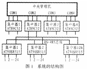
Through the central management machine and its software, managers can query the real-time and historical usage of water, electricity and gas in each household in the community according to the authority of the system password. The main function of the concentrator is to save the history and the current collected data. It acts as the slave of the collector and also serves as the slave of the central management machine, and can provide RS232, RS485 and integrated MODEN communication interface (standby). The collector acts as a counting device to sample the pulse signal. It can also notify the central management machine of the property when the line is disconnected to prevent someone from stealing electricity (water, gas). The collector has 24 channels, each of which can be separately set as an electric meter, a gas meter or a water meter pulse input; the input signal can be an active signal or a passive signal, and the pulse frequency is generally less than 10 Hz. The on-site collection instrument is used to record the amount of water, electricity and gas for the user, and output it in the form of electric pulse.
The central management machine communicates with the collector with timing acquisition (greater than or equal to 3 minutes) and active acquisition. The specific operation can be issued by the operator, which can automatically collect all channel data or data of a specific channel. The upper computer completes the following functions through the collector: setting the communication baud rate (default is 19200), setting the timing acquisition time of the concentrator to the collector, setting the collector time, acquiring the acquisition data in the concentrator, and Alarm signal, setting a collector data, reading a collector setting data, and opening and closing accounts.
The RS-485 half-duplex interface is used between the concentrator and the collector, and the master-slave mode is used for communication. In general, the concentrator collects data periodically or continuously to the collector. When the host computer communicates with the concentrator, it must wait for the concentrator to complete communication with a collector to start interactive data.
In this system, four concentrators are hung under the central management machine, and 126 collectors are connected under each concentrator. Since the RS-485 bus can hang up to 32 drives, in some collectors, a repeater should be set up (this repeater can be composed of two back-to-back MAX1487) so that the RS-485 bus can be hung 126. Collectors.
2.2 Communication Protocol
The communication protocol of the system includes a character format and a data packet format. In the character format, each character is asynchronous in transmission. The specific character format is as follows:
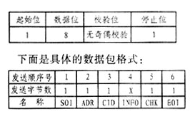
Among them, the start flag bit SOI (STARTOFIN-FORMATION) is 7EH, corresponding to the ASCII code character "~", representing the beginning of a new information frame.
The slave address ADR (ADDRESS) is the identification mark of each slave, and the slave of the same address cannot be attached to one data bus RS-485. The slave address ranges from 1 to 254, where 0 is reserved and 255 is the broadcast address.
The command identifier CID (COMMANDID) is an identification flag for each type of host to issue a command to the slave.
The information field INFO (INFORMATION) is data information and can be divided into two categories: command information and response information.
The checksum code CHK(CHKCODE) is an accumulation and check code of the three parts of ADR, CID and INFO.
The end marker EOI (ENDOFINFORMATION) is 0DH, corresponding to the carriage return, representing the end of an information frame.
2.3 pulse equivalent billing principle
The bills for water, electricity, and gas are generally measured by the number of output pulses of water, electricity, and gas meters. The actual usage and the amount payable can be calculated by the following formula: Q=NKR
In the formula, Q is the amount to be paid, N is the number of pulses, K is the water flow, electric power or gas flow represented by each pulse, and R is the unit price.
3 hardware connection circuit
3.1 Concentrator circuit
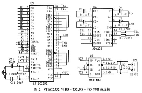
In the concentrator, the circuit connection of ST16C2552 with RS-232 and RS-485 is shown in Figure 2. The ADM202 in the figure converts RS-232 levels to TTL levels. The MAX1487 is a +5V powered RS-485 interface differential signal transceiver that selects whether to receive or transmit data via the P1.2 port of the CPU. At the same time, the TTL level can be converted into an RS-485 differential interface signal or reversed.
3.2 collector data acquisition circuit
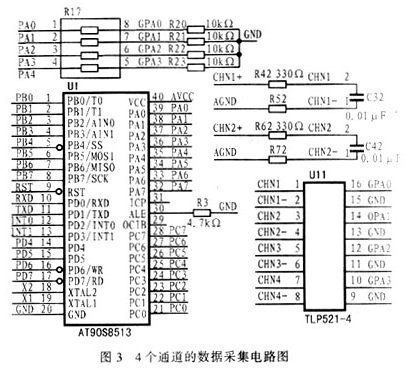
Figure 3 shows a data acquisition circuit with four cell-based smart meter reading system channels based on the hierarchical communication mode. They are connected to the PA0 to PA3 ports of the AT90S8515, and the remaining 20 data acquisition circuits are connected to the PA port. 4-position line and PB port and PC port. After the pulse output signal of the collector is optically isolated, it can be pulse counted by AT90S8515.
4 Concentrator communication program
In the concentrator, the two external interrupts INT0, INT1 of the AT89C52 can be used to receive data from the central manager and the collector, respectively. Normally, the pins IN-TA and INTB of the asynchronous communication chip ST16C2552 are inverted and connected to INT0 and INT1, respectively. When the ST16C2552 receives the data, it will request an interrupt from the CPU to process the data. The following program snippet is written in C language. Its function is to initialize the ST16C2552 and prepare it for the concentrator to receive data.
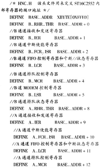
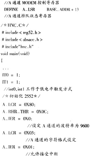
The following describes the workflow of the communication interruption service program by taking the data frame from the central management machine as an example. The specific process is as follows:
1 Turn off external interrupt 0 to prevent interrupt nesting.
2 Open external interrupt 0, judge whether the data frame start character SOI is received, and if so, prepare to receive the next character; if not, discard the received character.
3 Open external interrupt 0 to judge whether the received character is the local address. If yes, prepare to receive the next character; if not, discard the received character.
4 Receive data and the command control word, set the length of the data information to be received according to the control word, and open the external interrupt 0.
5 It is judged whether the data information is received or not. If not, the data information is continuously received. If the reception is completed, it is ready to receive the data frame end character EOI and open the external interrupt 0.
6 Determine whether the received data is EOI. If yes, set the data frame flag to 1, if not, discard all received data. Open external interrupt 0.
5 Conclusion
With the development of computer technology and network technology and people's pursuit of high quality life, community intelligence has become a trend of residential community development. The smart meter reading system is the most basic subsystem of the intelligent community, and its impact on the intelligentization of the community is obvious. Therefore, the further development of the intelligent meter reading system has broad application prospects.
915 MHZ wireless digital/special meter reading communication system design of the antenna.The antenna standing wave ratio performance is good, small dimension, structure, easy installation, stable performance, has the very good anti vibration and aging.
1. Features
GSM 915MHz Rubber Duck whip pcb Antenna for radio transceiver Walkie Talkie
Good appearance
Durable, corrosion resistance
Full day for working
Optimized dimension
High Gain, Lower VSWR, Strongly Anti-interference
Easy to install and adjust
2. Specification
Frequency Range: 915MHz
Gain: 3 dBi
VSWR: ≤1.5
Input Impedance: 50 Ω
Polarization: Vertical
Max Input Power: 20 W
Connector Type: SMA
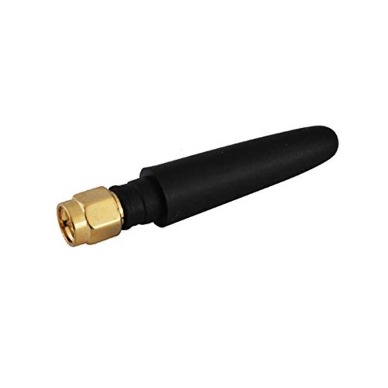
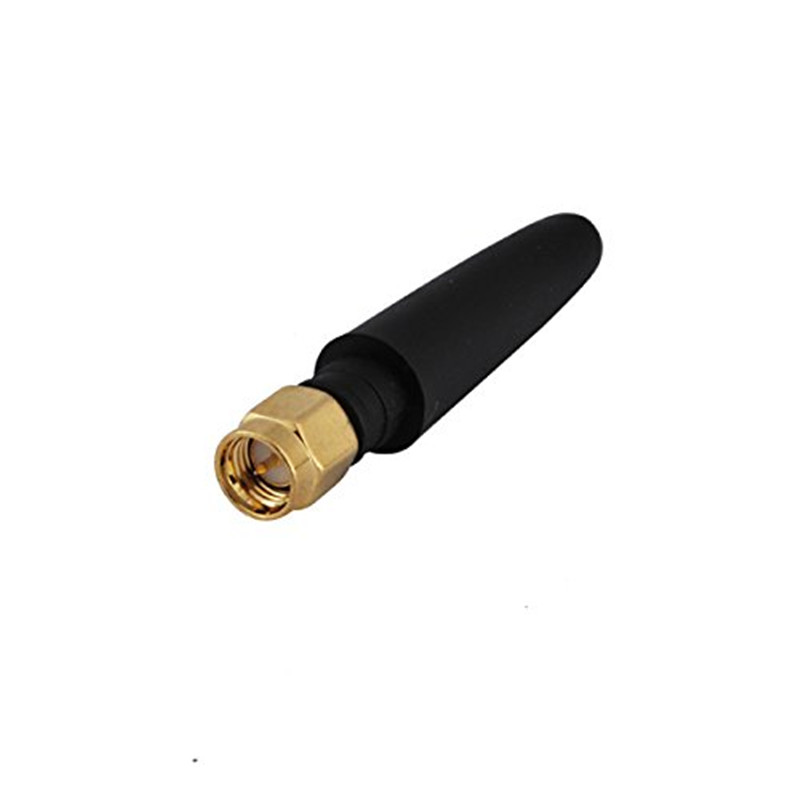
915mhz Antenna
915mhz Antenna,Mini 915mhz Antenna,Rubber 915Mhz Antenna,GSM Wireless Vertical Antenna
Shenzhen Yetnorson Technology Co., Ltd. , http://www.yetnorson.com