The Digital Addressable Lighting Interface (DALI) protocol is the next generation of lighting control protocols emerging in the field of lighting control. This paper introduces the working principle, system composition and system design method of DALI protocol. The PIC chip is used to implement the hardware architecture of the system, the command code used for communication between the computer and the system is defined, and the system application software and hardware interface driver are designed.
0 Preface
With the advancement of society and the improvement of the quality of life, people's requirements for lighting equipment are no longer satisfied with simple switch control, but an intelligent lighting control system with energy saving, high efficiency and flexible operation is needed. At present, there are many kinds of lighting control protocols commonly used, among which the Digital Addressable Lighting Interface (DALI) protocol is characterized by its low development cost, small system development difficulty, easy expansion, and practicability, and is displayed in the field of intelligent lighting control. Strong advantage.
1 DALI protocol
The DALI protocol is an open asynchronous serial digital communication protocol for lighting system control. The DALI system adopts a master-slave structure. The system can connect up to 64 slave units. Each DALI slave uses a unique individual identification address. This address is set during system initialization. The slave address can be modified according to requirements during use. The slave unit can be divided into up to 16 groups (differentiated by group address). Each slave can belong to several different groups, and each group of devices can set 16 scenes. The two signals are used to communicate between the master and the slave. The data is encoded in Manchester encoding. The rising edge of the signal indicates “1â€, the falling edge indicates “0â€, and the communication rate is 1.2 kbaud/s. The host uses two different data frame formats during communication: the transmit frame (the master sends to the slave) and the receive frame (the slave sends to the master). The DALI protocol defines a two-byte instruction set for implementing system functions. The instructions are divided into two categories: standard instructions and dedicated instructions. The first byte of the standard instruction is the address byte for addressing the DALI slave; the second byte is the command byte, which is used to control the addressed DALI slave. Using standard instructions, the main controller can implement group control, dimming control, scene setting and other functions for DALI slaves. The dedicated command does not contain the address byte. The two bytes are command codes and are sent by broadcast. They are mainly used to initialize the address of the DALI system.
3. 1 master design
The main controller uses the PIC16F877 microcontroller as the CPU. The PIC16F87X family of microcontrollers is a high performance 8-bit CMOS microprocessor from Microchip Corporation of the United States. The PIC16F877 has five I/O ports, RA, RB, RC, RD, and RE. In addition to the general-purpose I/O functions, these ports also have different dedicated functions, such as PWM output, counter input, and external level interrupt. , I2C bus interface, etc. The PIC16F877's dedicated registers and general-purpose registers are uniformly addressed, for a total of 368 8-bit wide RAM cells (some cells remain unused). The system main controller is composed of DALI module, RS2232 module, display control module and power supply. The system structure is shown in Figure 1.
3. 2 slave design
The DALI ballast is used as a DALI slave in the system. The DALI ballast consists of two parts, DALI and ballast control. This system uses the PIC16F877 as the DALI chip and the UBA2104 as the ballast controller.
The PIC16F877's EEPROM stores the parameters of the DALI ballast, such as the current intensity level, the ballast power-on level, individual address, search address, random address, group ID, scene intensity value, status information, version number, and so on. The parameters of the ballast are set by the main controller during system initialization. After the ballast receives the initialization command, it calls the EEPROM write operation to write the parameters to the EEPROM. It can be modified as needed during the running process.
The on-chip EEPROM of the PC16F877 has a total of 256 bytes and an address range of 00H to FFH. The slave's DALI software is similar to the host's DALI software design. The difference is that the DALI data received by the main controller is single-byte data, and the double data is sent; the slave receives double-byte data and sends single-byte data. Therefore, in terms of software design, the DALI of the slave and the DALI of the host differ only in the number of bits of data received and transmitted. The slave DALI hardware uses optocoupler to acquire data from the DALI bus. The optocoupler circuit isolates the interference on the one hand and converts the logic signal to a CMOS level on the other hand. The PIC16F877 chip of the ballast receives the data from DALI and selects different processing calls depending on the command (each command has a corresponding handler). These handlers modify the slave state parameters in the EEPROM, convert the brightness level in the DALI control command to the corresponding pulse width modulation (PWM) signal output, and the PWM signal is converted to an analog signal of 0 to 10 V through the RC converter circuit. Go to UBA2014 and control the brightness of the lighting.
4 Conclusion
This paper introduces the hardware and software design of DALI control protocol using PIC microcontroller, discusses how to achieve high-reliability intelligent lighting control, and analyzes the working principle of DALI protocol in detail.

Medical Device speaker:
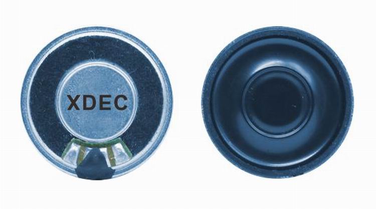
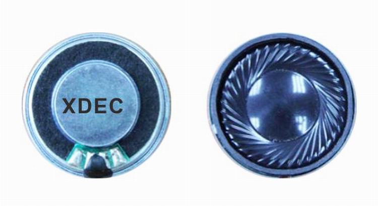
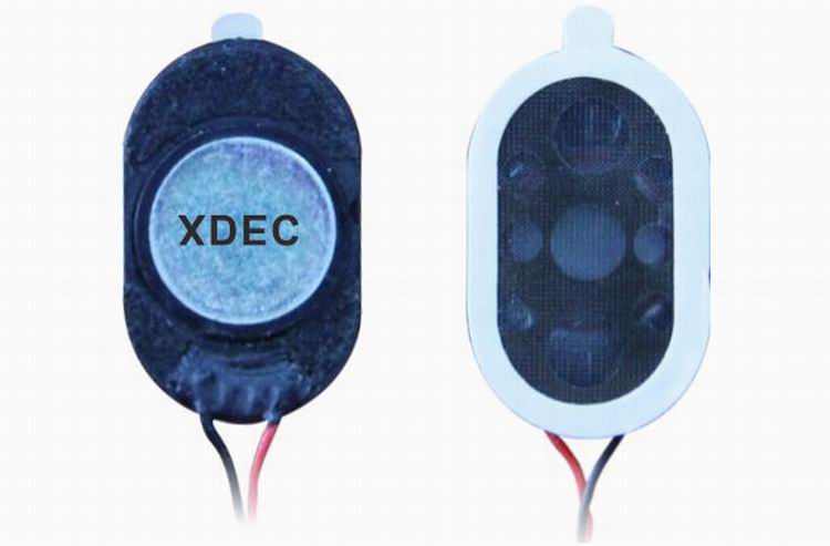
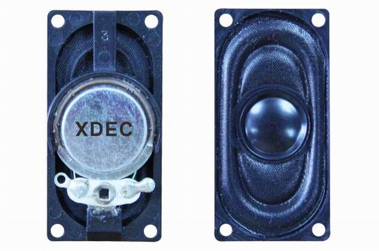
Medical Device speaker is a kind of micro speaker unit which uses a diaphragm made of Mylar material. Mylar speakers are of ultrathin design and lightweight and clear voice. It is widely used in medical devices (sphygmomanometer, glucometer, fetus-voice meter-) .
There are two types of Mylar speakers from the shapes:
1) Round shapes, we have products from 10mm to 57mm in diameter.
2) Oblong shape, we have products in sizes of 1510/1712/1813-..


FAQ
Q1. What is the MOQ?
XDEC: 2000pcs for one model.
Q2. What is the delivery lead time?
XDEC: 15 days for normal orders, 10 days for urgent orders.
Q3. What are the payment methods?
XDEC: T/T, PayPal, Western Union, Money Gram.
Q4. Can you offer samples for testing?
XDEC: Yes, we offer free samples.
Q5. How soon can you send samples?
XDEC: We can send samples in 3-5 days.
Sphygmomanometer Speaker,Fetus-Voice Meter Speaker,Glucometer Speaker,Blood Pressure Monitor Speaker
Shenzhen Xuanda Electronics Co., Ltd. , https://www.xdecspeaker.com