Research on Evaluation Method of Light Distribution Performance of Automobile Headlamp Based on Subjective Evaluation Experiment
Wang Wei 1 , Lin Yandan 2 , Bu Wei Li 1
(1. Shanghai Motor Vehicle Testing Center, Shanghai 201805; 2. Fudan University, Shanghai 200433)
Abstract: CIE188 Technical Report released an objective calculation method for evaluating the light distribution performance of automotive headlamps, which can be used for quantitative evaluation of the light distribution performance of headlamps. A set of dedicated software has been developed to assist in the implementation of this evaluation calculation. In addition, in order to verify the applicability of the method in China, this paper carried out a subjective evaluation experiment on the light distribution performance of four sets of headlamps to explore the correlation between the subjective evaluation experiment results and the calculation results according to the CIE188 technical report. The experimental results show that the evaluation method of the light distribution performance of the automobile headlights in the technical report of CIE188 can achieve the comparison between the light distribution performance of different headlights, but the correlation between the results obtained by the two methods is not significant.
Key words: CIE 188 technical report; light distribution performance; quantitative evaluation; subjective evaluation
CLC number: TM923 Document code: A DOI: 10.3969∕j.issn.1004-440X.2015.02.023
Experimental Verification of Performance Method for Vehicle Headlighting Systems
Wang Wei 1 , Lin Yandan 2 , Bu Weili 1
(1.Shanghai Motor Vehicle Inspection Center, Shanghai 201805, China; 2.Fudan University, Shanghai 201805, China)
The evaluation of the photometric performance of vehicle headlamps with a standardized ,accurate and reliable method, the CIE 188 Technical Report specifies a set of certain methods to assess the photometric performance of vehicle headlighting systems . The assessment can be achieved with a self - Developed software. Three subjective rating tasks were conducted to verify the rationality of the methods described in this report and the suitableness with Chinese subjects . The comparison between the reported calculated according to CIE 188 Technical Report and subjective rating scores indicated there's no significant correlation between the Two methods. It is necessary to do further research on the methods described in this report.
Key words: CIE 188 Technical Report; photometric performance; evaluate; subjective rating
introduction
There are strict requirements on the light distribution of automobile headlights in countries all over the world. China adopted the standard of ECE system, and since 1993, it has successively formulated national mandatory standards for automotive lighting [1] . According to the type of light source, there are currently three national standards related to light distribution of automobile headlamps, namely GB 4599-2007 "Lighting bulb headlamps for automobiles" and GB21259-2007 "Gas discharge headlights for automobiles" and GB 25991—2010 “LED headlamps for automobiles†[2 -4] . The principle of these national standards is to define the range of illumination of the car within the safe braking distance. Therefore, the light distribution performance test of the headlights according to the national standard can only qualitatively judge whether the headlights are qualified or not, and cannot quantitatively evaluate the advantages and disadvantages of the headlights.
In 2010, the Fourth Division of the International Commission on Illumination (CIE) (Lighting and Optical Signaling Division) released the Technical Report No. 188 “Performance Assessment Method for Vehicle Headlighting Systems†(in this paper) Referred to as CIE188 report), a set of calculation methods for the evaluation of light distribution performance of motor vehicle headlamp system is introduced in detail [5] .
This method quantitatively evaluates the light distribution performance of the headlights from the aspects of road surface illumination and glare control. Therefore, according to this method, the light distribution performance comparison between different headlamp systems can be achieved. However, there is no open special software that can be calculated according to the calculation method specified in the CIE188 report. The use of manual calculations is not only inefficient, but also prone to errors. The development of supporting computing software is extremely necessary for the development of research. Therefore, this study developed a dedicated headlamp light distribution performance calculation software for implementing the various calculation functions of the headlights in the CIE188 report. In addition, since there is no research results in China indicating the applicability of this method in China, this paper also carried out a series of subjective evaluation experiments, using the results of the light distribution performance calculated by the method specified in the CIE188 report and the subjective evaluation results of the subjects. Correlation between.
1 Research methods
1.1 Experimental setup
The research in this paper is divided into two parts. The first part is the verification of software precision. The accuracy of the software is verified by comparing the ground illuminance value of the software output with the ground illuminance value simulated by LMT's fully automatic luminaire grading analysis system. In the second part, this paper conducts subjective evaluation experiments on 4 sets of headlamp systems (referred to as A, B, C, D systems, respectively, as shown in Figure 1), and reports subjective evaluation results and reports according to CIE188. The objective calculation results in the correlation analysis were carried out to verify the applicability of the method for evaluating the light distribution performance of the headlights in the CIE 188 report.
1.2 The function of the headlight light distribution performance calculation software
There is a set of LMT company's automatic light distribution detection equipment in the laboratory, which is used for the light distribution scanning equipment of many lamps used by many testing institutions at home and abroad, as shown in Figure 2. The device can obtain the illuminance value on the vertical plane 25 meters ahead of the headlight according to the preset scanning accuracy, with high precision (U rel =5%, k =2). The scanning method of the headlamp light distribution data as shown in Fig. 3 is specified in the CIE188 report.
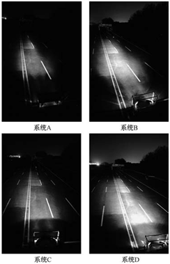
Figure 1 The light pattern to be evaluated
Fig.1 Plan view of the headlamps
According to this scanning method, the original scan data of the left (or right) light of each low beam (or high beam) is 111185 illuminance values ​​on the vertical light distribution screen 25 meters ahead of the headlights. Using these raw data, the study completed the following calculation steps through the headlamp light distribution performance calculation software:
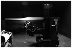
Figure 2 LMT automatic lighting distribution analysis system
Fig.2 LMT photometric testing system
(1) Using the original scan data of the left and right lights, calculate and merge the illuminance data on the vertical light distribution screen at the front 25 meters when the left and right lights are simultaneously illuminated;
(2) Converting the illuminance value of the headlamp on the vertical light distribution screen at 25 meters to the vertical illuminance value on the horizontal surface of the road surface and any height from the ground;
(3) Using the interpolation method, find the 1lx, 3lx and 5lx illuminance points on the road surface and the horizontal plane at any height from the ground, and draw the illuminance curves such as 1lx, 3lx and 5lx;
(4) Using the data and graphs obtained in steps (2) and (3), calculate the light distribution performance evaluation indicators of the headlamps to be tested according to the light distribution performance calculation method described in the CIE188 report.
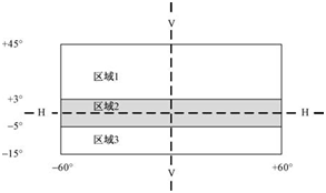
Zone 1 and Zone 3: 0.2° in the horizontal direction and 0.5° in the vertical direction
Zone 2: 0.2° in the horizontal direction and 0.1° in the vertical direction
Figure 3 Scanning accuracy of headlamp light distribution data
Fig.3 Zones of test point matrices
1.3 Subjective evaluation experiment task
The experiment took place after dark, from 19:00 to about 1 am the next day. In the experiment, the controllable lighting fixtures around the site were all closed, ensuring that the experimental ambient illumination was less than 0.1 lx. The experimental site is a 6-lane road that simulates a real road (some open spaces on both sides of the lane), as shown in Figure 4. Each lane is 3 meters wide and approximately 200 meters long. Due to the size limitation of the site, the high beam test is inconvenient. This experiment only studies the low beam. During the experiment, the low beam light is installed on the experimental fixed platform according to the actual loading parameters,
Simulate the actual lighting effect of the headlights on the vehicle, and fix it in the center of a certain lane in the middle (the left and right low beam longitudinal axis passes through the lane), as shown in Figure 5.
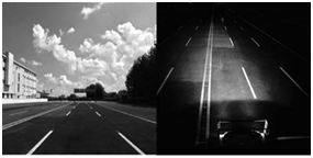
Figure 4 Experimental field map (left image taken at 14: 00, right image taken at 20: 00)
Fig.4 Test site
1.3.1 Experimental task 1: Low beam illumination distance assessment
Figure 6 shows a schematic diagram of the evaluation of the distance of the low beam illumination. The experimental task is the subject's detection of the visual target on the specified axis (here "probe" means that the subject can find the visual target). Used in the experiment
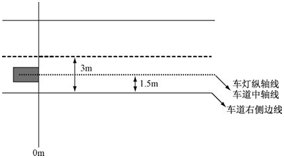
Figure 5 Position of the headlights on the driveway in the experiment
Fig.5 The position of the headlamps on the road
The visual target is a dark gray cube with a surface reflectance of 5% and a side length of 400 mm. The visual target appears on the right side of the lane and on the longitudinal axis of the lane. In the experiment, the method was gradually advanced from near to far, and the subject was identified from 100 meters away from the headlights. If it could not be identified, the visual target was advanced 10 meters to continue identification until the subject could detect the target. The distance between the target and the lamp is used as the irradiation distance of the low beam. In order to avoid the expected effect, the bezel is covered by the baffle during the advancement of the box.
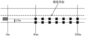
Figure 6 Schematic diagram of the evaluation of the distance of the low beam illumination
Fig.6 Passing beam range evaluation
In order to fix the observed eye position of the subject, the subject needs to identify the front visual target through the rectangular square hole on the left side of the observation screen during the whole experiment. The observation screen is placed 0.5m behind the fixed platform of the lamp. The viewing screen size is shown in Figure 7.
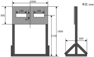
Figure 7 Low-beam illumination distance width evaluation experiment observation screen
Fig.7 View screen arrangement used for range and width evaluation
1.3.2 Experimental task 2: Evaluation of the width of the low beam illumination
Figure 8 shows a schematic diagram of the evaluation of the low beam illumination width. The experimental task is the detection of visual targets on both sides of the lane at the specified distance. The subjects identified the visual targets on both sides of the 10m, 20m, 30m, 40m and 50m front lights in front of the headlights. The distance of the detectable visual target from the longitudinal axis of the lane was taken as the beam illumination width of the lamp at this distance. The visual target and viewing screen size are the same as in Experimental Task 1.
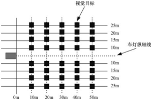
Figure 8 Schematic diagram of the evaluation of the illumination width of the low beam
Fig.8 Passing beam width evaluation
1.3.3 Experimental Task 3: Evaluation of the glare of the low beam
Figure 9 shows a schematic diagram of the evaluation of the glare of the low beam. The subjects stood in the center of the left lane 50m away from the lights, and observed the visual targets placed in the center of the left lane 10m away from the lights through the screen, and evaluated according to the De Bore evaluation scale (as shown in Table 1). The glare feeling brought by the lights under this observation condition. Taking into account the height of the eye position of three typical vehicle drivers, such as ordinary cars, SUV models and trucks, the observation hole is set to three rows of holes of different heights, the heights of the ground are 950mm, 1150mm and 1500mm respectively, as shown in Figure 10. Show.
Table 1 De Bore Evaluation Scale
Table 1 De Bore rating
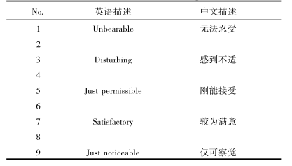
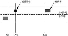
Figure 9 Schematic diagram of the evaluation of the glare of the low beam
Fig.9 Passing beam opposing glare evaluation
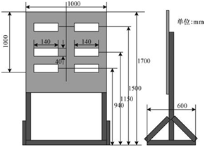
Figure 10 Low-beam glare evaluation experiment observation screen
Fig.10 View screen arrangement used for opposing glare evaluation
1.3.4 Experimental process
Before the start of the experiment, proceed as follows:
(1) Scan the light distribution data of four sets of headlamps to be tested in the laboratory with LMT automatic lamp light distribution analysis system. The scanning accuracy is in accordance with the accuracy specified in the CIE188 document.
(2) The actual loading parameters of the four sets of headlamps are measured and recorded in Table 2.
(3) According to the parameters recorded in Table 2, four sets of headlamps to be tested are initially calibrated in the laboratory.
(4) Use the positioning instrument at the experimental site to locate the points to be used in the experiment on the site and mark them with a marker and a reflective marker.
(5) Install the headlamp to be evaluated to the fixed test bench according to the parameters recorded in Table 2.
(6) Close all controllable lighting equipment around the test site, measure the ambient illuminance with a illuminometer, and ensure that the experiment is started after less than 0.1lx.
(7) Light up the low beam and warm up for 10 minutes.
Table 2 Headlight loading parameter table
Table 2 Installation data of the headlamps

After completing the above preparatory work, three sets of headlamps were tested according to the requirements of the experimental task, and the three evaluation experiments of irradiation distance, irradiation width and glare were completed. The entire experiment was designed in-group. A total of 8 participants participated in the experiment, and each participant completed all the evaluation tasks of the four headlamps. These subjects are between the ages of 21 and 35 and have a bachelor's degree or above. Some subjects had different degrees of visual myopia, but their vision was corrected by wearing glasses to achieve a visual acuity of 1.0 or more. All participants in the experiment did not have color blindness or color weakness.
2 Experimental results
2.1 Software Verification
One of the main objectives of this paper is to verify the correlation between the scores of indicators such as the distance and width of the headlights actually evaluated and the results calculated according to the method specified in the CIE188 report. The latter results mainly depend on the headlamp light distribution performance calculation software developed in this paper. The accuracy of the software calculation results will directly affect the results of this paper. Therefore, it is necessary to verify the accuracy of this software. In this paper, the results of the headlight light distribution performance calculation software are compared with the results of the LMT LIMES 2000 software of the LMT automatic light distribution analysis system to achieve the verification purpose.
2.1.1 Light type contrast
Using the illuminance value on the vertical plane 25 meters ahead of the headlamp, combined with the lamp loading parameters, the headlamp light distribution performance calculation software developed in this paper and the LMT LIMES 2000 can simulate the lamp by calculating the ground illuminance value. Light pattern on the road surface. Figure 11 shows the illumination patterns of the ground 1lx, 3lx and 5lx illuminance curves of two sets of low beam lights simulated by two softwares. As can be seen from the two figures, the light patterns of the two sets of software output are very consistent.
2.1.2 Comparison of illuminance values
In order to further verify the accuracy of the ground illuminance value calculated by the software, this paper calculates the light distribution data of a set of headlamps with two sets of software, and randomly selects 13 ground illuminance values ​​calculated by software, and performs two sets of software. Comparison of illuminance values. The calculation results of the two sets of headlights are shown in Figure 12. Ground illuminance value calculated by two sets of software
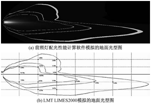
Figure 11 Illumination curves of ground 1lx, 3lx and 5lx for two sets of software simulation outputs
Fig.11 Light distributions of headlamps outputted by the aided software and LMT LIMES 2000 software
The difference is basically below 1lx, and the average difference percentage is about 6%.
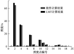
Figure 12 Comparison of two sets of software output ground illumination
Fig.12 Vertical illuminance outputted by the aided software and LMT LIMES 2000 software
2.2 Headlights light distribution performance calculation results
Using the headlamp light distribution performance calculation software, this paper calculates the light distribution performance evaluation scores of the four sets of low beam lamps used in the experiment, as shown in Table 3. Obviously, the larger the score of the evaluation index other than glare, the better the light distribution performance. A Friedman test was performed on the light distribution performance calculations (except for glare) of the four headlamps. The results showed that there was a significant difference between the four systems (p = 0.002), and the scores were ranked from high to low as C > D > A >B. It can be seen that the two sets of HID low beam lights in the experiment (except glare) are higher than the halogen source low beam.
Table 3 Calculation results of light distribution performance of four sets of low beam samples
Table 3 Results of photometric performance calculated by the software

2.3 Subjective evaluation of experimental results
Table 4 shows the results of the subjective evaluation experiments of this experiment. The Friedman test was also performed on the evaluation indicators other than glare. The results showed that there were significant differences between the four systems (p = 0.013), and the scores were ranked from high to low as C > D > A > B; the same two sets of HID light sources The system score is higher than the system scores of the two sets of halogen sources. A Friedman test of the glare scores showed no significant difference between the four systems (p = 0.183); however, the repeatability test showed a significant difference in glare evaluation scores between the three observed heights (p = 0.008). .
Table 4 Subjective evaluation experiment results
Table 4 Subjective rating scores

2.4 Correlation analysis
In order to verify the correlation between the objective calculation results and the subjective evaluation results in the CIE188 report, the calculation results of the two methods are further compared. The results are shown in Fig. 13 to Fig. 15. As can be seen from the figure, in addition to the glare score, the two methods have a good agreement between the irradiation distance and the irradiation width. However, further pearson correlation analysis showed that there was a significant correlation between the two results except the curve width of the curve (p = 0.019), and the correlation between the two results of the other indicators was not significant.
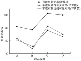
Figure 13 Comparison of calculation results of irradiation distance and subjective evaluation results
Fig.13 Passing beam range-compassion of calculation and observation results
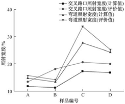
Figure 14 Comparison of calculation results of irradiation width and subjective evaluation results
Fig.14 Passing beam width-compassion of calculation and observation results
3 Discussion
3.1 Software Verification
This paper compares the calculation results of the headlamp light distribution performance calculation software with the calculation results of the software of the LMT automatic light distribution analysis system to verify the accuracy of the software developed in this paper. From the comparison of the ground light distribution type of the low beam, the light output of the two sets of software is the same. Further comparison of two sets of software
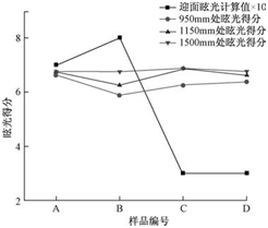
Figure 15 Comparison of calculation results and subjective evaluation results of glare evaluation
Fig.15 Passing beam opposing galre-compassion of calculation and observation results
When calculating the ground illuminance value, there are some differences between the results of the two algorithms. There are two possible reasons: First, in the development of the software, when the separate light distribution data of the left and right lamps of the headlights are merged into the light distribution data of the simultaneous illumination, only the overlapping portions are added, possibly with the LMT. There are differences in the software algorithms; second, the interpolation methods used are different.
3.2 Correlation between objective calculation results and subjective evaluation results
The main purpose of this paper is to verify the applicability of the headlamp light distribution performance evaluation method introduced in China in the CIE188 technical report by subjective evaluation test of Chinese people. Although the method in the CIE Technical Report describes the calculation of the various indicators of the headlamps, it does not stipulate the method of obtaining the comprehensive score through multiple evaluation indicators. Therefore, the research in this paper does not give a comprehensive score for each set of headlamps. However, relying on statistical methods, it is still possible to evaluate the quality of the four sets of lamps according to the scores of multiple indicators. In the same way, the subjective evaluation experiment results can also provide a basis for comparing the scores of the light distribution data of the four sets of lamps through statistical methods. The results of this paper show that the light distribution data of the four sets of lamps, in the case of uncombined glare fraction, the ordering of the light distribution performance under the two methods is consistent. However, further correlation analysis results did not indicate a significant correlation between the results of the two methods. The reason may be related to the small sample size used in this paper. In subsequent studies, the sample size should be increased for further analysis.
4 Conclusion
The headlamp light distribution performance software developed in this paper can be used for the calculation of the headlamp light distribution performance method described in the CIE188 technical report, and the accuracy of the results can be guaranteed. In addition, through the experiments in this paper, it is proved that the calculation method of the headlamp light distribution performance in the CIE188 technical report can be used to compare the light distribution performance of different headlights. The comparison results obtained by this method are consistent with the results of subjective evaluation of the light distribution performance of the headlights. However, the correlation between the two results is not significant, and it is still necessary to further verify the results by increasing the sample size.
references
[1] Huang Zuoxian. Modern Auto Lamps [M]. Beijing: Changhong Publishing Company, 2003: 290.
[ 2 ] General Administration of Quality Supervision, Inspection and Quarantine of the People's Republic of China, China National Standardization Administration Committee. GB 4599—2007 Filament Bulb Headlamps for Automobiles [S]. Beijing: China Standard Press, 2008.
[ 3 ] General Administration of Quality Supervision, Inspection and Quarantine of the People's Republic of China, China National Standardization Administration Committee. GB 21259—2007 Gas discharge light source headlights for automobiles [S]. Beijing: China Standard Press, 2008.
[ 4 ] General Administration of Quality Supervision, Inspection and Quarantine of the People's Republic of China, China National Standardization Administration Committee. GB 25991—2010 LED headlamps for automobiles [S]. Beijing: China Standard Press, 2011.
[ 5 ] CIE Central Bureau.Performance assessment method for vehicle headlighting systems [R].Vienna: CIE, 2010.
HD Slip Ring is an electromechanical device. It allows the transmission of power and signals from a stationary to a rotating structure. It consists of an electrically conductive rotating ring, with one or more stationary contacts. They are called "stations" or "spokes". Electrical signals (power and/or data) are transmitted through the slip ring. This is done by means of brushes that make contact with the ring.
It is typically used where there is a need to rotate one object relative to another. Especially for passing power and/or signals from the stationary object to the rotating object.
Regarding it's application in conjunction with other equipment, we'll need high-quality production. Oubaibo uses components imported from the United States and high-frequency signal processing. Which has the characteristics of small size, lightweight, good insulation performance, stable transmission, and so on. Its unique design makes it an ideal choice for many applications.
Hd Slip Ring,Slip Ring Power,Fiber Optic Slip Rings,Small Slip Rings
Dongguan Oubaibo Technology Co., Ltd. , https://www.sliprobs.com