Systems with moving mechanical components often have to measure what is spinning.
This article refers to the address: http://
In a car, the speed of the wheel is measured using a speedometer, a traction controller, an anti-lock brake, and a cruise controller. The engine's revolutions per minute (RPM) should be monitored to control the transmission so that the vehicle speed remains below the maximum safe speed. Power windows are typically controlled by a small motor with closed loop rotation detection. And let's not forget that when your favorite song starts playing, the radio system needs to detect the volume knob (when you turn the knob).
In addition to cars, the rotary inspection technology is suitable for many other applications and is used in motor shafts, fans, gears, turbines and computer mouse wheels. This figure shows an example of using this technique to determine fluid flow rate:
This type of sensor is called a rotary encoder and is divided into two categories: absolute encoders (which can tell the exact position in degrees) and incremental encoders (which detect relative changes). A simple example of an absolute encoder is a potentiometer.
Within the scope of incremental encoders, the two main types are "speed mode" and "speed and direction". The first type: When any rotation occurs, the sensor can only generate pulses and cannot distinguish between clockwise rotation and counterclockwise rotation. The second type: direction information can be added, and the addition task of the direction information is completed by adding another sensor; then the controller in the system can judge the order of transition between the two sensors to know in which direction to turn.
Popular detection method for incremental encoders
The three most common technical methods for incremental encoders are mechanical, optical, and magnetic.
Mechanical technology method: This type of method is contact type, in which the metal brush on the rotating piece can selectively contact the metal area on the stator. On a printed circuit board (PCB), a voltage can be applied to a terminal, and the presence of a voltage can be measured at the switching terminal when rotation occurs. This is the most primitive method with several disadvantages:
Friction on the contact surface causes the contact surface to wear over time.
The contact surface will not work well in the presence of contaminants such as dirt and corrosion products.
Bandwidth (detected per second) is largely limited by the brush's debounce time (which can be on the order of milliseconds).
The mechanical design and assembly process can be somewhat complicated.
Optical Technology: This type of method usually requires a disk with a small hole (mask) cut out, one light-emitting diode (LED) on one side and two photodetectors on the other side. The highest resolution optical encoders that any other type of encoder can achieve can achieve thousands of pulses per revolution, but with consequent tight manufacturing and alignment tolerances. Applications range from computer mouse wheels to high-end semiconductor lithography equipment. A common disadvantage is its lack of robustness in harsh industrial environments, as any physical contaminant blocks light, and sensing can be a problem. In addition, the lifetime of the LED will be shortened at high temperatures.
Magnetic Technology: A 3-pin Hall-effect integrated circuit (IC) and a small magnet on a rotating piece are a surprisingly simple yet robust method for measuring speed. The DRV5033-Q1 is very suitable here. The sensor can be completely enclosed, isolated from the environment, and the magnetic field of the magnet can travel a distance away from most types of contaminants between the two.
To measure speed and direction by magnetic technology, the standard solution is to use two latched Hall sensors and a ring magnet alternating with the north and south poles. For example, DRV5013-Q1 and a magnet like this. As shown in the figure below, when each sensor is close to the South Pole, it produces a low level output; when it approaches the North Pole, it causes a high level output. The output produced by the two sensors is called the quadrature output - this is an elegant name for signals with a phase difference of 90°.
For any given 2-bit state, there is a unique 2-bit state for clockwise increments and another unique 2-bit state for counterclockwise increments. Therefore, the microcontroller firmware is fairly simple.
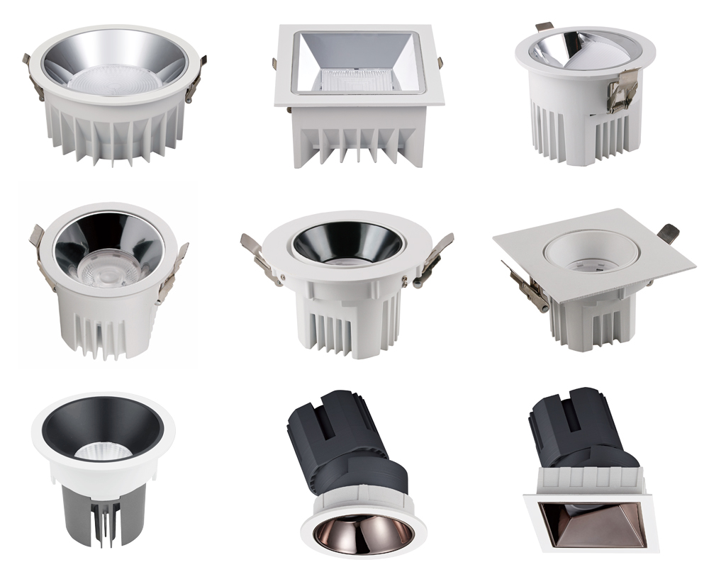
Here you can find the related products in Led Down Light, we are professional manufacturer of LED Down Light, waterproof Down Light, Led Down Light, Square Ip65 Light, Recessed Down Light, RA90 down Light, IP54 Down Light. We focused on international export product development, production and sales. We have improved quality control processes of LED Down Light to ensure each export qualified product.
If you want to know more about the products in LED Down Light, please click the product details to view parameters, models, pictures, prices and other information about the led down light. Whatever you are a group or individual, we will do our best to provide you with accurate and comprehensive message about LED Down Light!

LED Down Light
Waterproof Down Light,Led Down Light,Square Ip65 Light,Hotel Down Light
Guangdong Decosun Lighting Technology Co.,Ltd , https://www.decosun-lighting.com