Reset is the initialization operation of the microcontroller. When the MCU is running, it needs to be reset first. Its function is to make the CPU and other components in the system in a certain initial state and start working from this state. Thus, resetting is a very important mode of operation. However, the MCU itself cannot be automatically reset, and must be implemented in conjunction with the corresponding external circuit.
Reset circuit:
When the reset pin RST (full name RESET) of the MCS-5l series MCU appears at a high level for more than 2 machine cycles, the MCU performs a reset operation. If RST continues to be high, the microcontroller is in a cyclic reset state.
Depending on the requirements of the application, there are usually two basic forms of reset operation: power-on reset and power-on or switch reset.
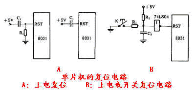
The power-on reset requires a reset operation after the power is turned on. The commonly used power-on reset circuit is shown in the left figure in Figure A. In the figure, the capacitor C1 and the resistor R1 constitute a differential circuit for the power supply of 10V. After power-on, keep RST for a high time. Due to the equivalent resistance in the microcontroller, the operation function of power-on reset can be achieved without the resistor R1 in the figure, as shown in the right figure in the figure (A) below.

After the power-on or switch reset requires the power to be turned on, the MCU automatically resets, and during the operation of the MCU, the MCU can also be reset by the switch operation. A commonly used power-on or switch reset circuit is shown in Figure (B) above. After power-on, due to the charging of capacitor C3 and the action of the inverting gate, RST is held high for a period of time. When the MCU is already running, pressing the reset button K and releasing it can also make RST a high level for a period of time, thus realizing the operation of power-on or switch reset.
According to the actual operation experience, the capacitance and resistance reference values ​​of the two reset circuits are given below.
In the above figure (A): Cl=10-30uF, R1=1kO
In Figure 1.27(B) above: C:=1uF, Rl=lkO, R2=10kO
The status of the microcontroller after reset:
The reset operation of the microcontroller causes the microcontroller to enter the initialization state, which includes making the program counter PC = 0000H, which indicates that the program starts execution from the 0000H address unit. After the MCU is cold-started, the on-chip RAM is a random value. The reset operation in the operation does not change the contents of the on-chip RAM area. The state after the reset of the 21 special function registers is the determined value, as shown in the following table.
It is worth pointing out that remembering the main state after resetting some special function registers is very necessary to understand the initial state of the microcontroller and reduce the initialization part of the application.
Description: The symbol * in the table is in a random state;
A=00H, indicating that the accumulator has been cleared;
Accusure Pulse Oximeter,Blood Oxygen Meter,Spo2 Monitor,Spo2 Sensor
GANSU PINGLINAG ABAY SCIENCE&TECHNOLOGY CO.,LTD , https://www.yzwtech.com