The black box test is also called the function test. It is tested to check whether each function can be used normally. In the test, the program is regarded as a black box that cannot be opened. It is tested at the program interface without considering the internal structure and internal characteristics of the program. It only checks whether the program function is normally used according to the requirements specification. Whether the program can properly receive input data to produce correct output information. The black box test focuses on the external structure of the program, regardless of the internal logic structure, and mainly tests the software interface and software functions.
The black box test is based on the user's perspective and tests from the correspondence between the input data and the output data. Obviously, if the external features are designed with problems or the specifications are incorrect, the black box test method cannot be found.
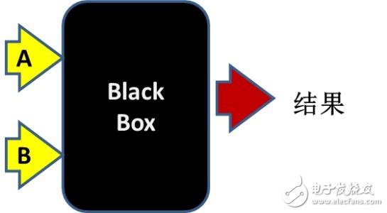
There are seven test methods in the black box test: equivalence class division method, boundary value analysis method, error estimation method, causal map method, decision table driving method, function chart method, and orthogonal experiment method. The following will be introduced one by one.
Equivalence class divisionThe equivalence class division divides all possible input data, that is, the input field of the program into several parts (subsets), and then selects a few representative data from each subset as test cases. This method is an important, commonly used black box test case design method.

1. Divide equivalence classes:
An equivalence class is a subset of an input field. In this subset, each input data is equivalent to the error in the disclosure procedure. It is reasonable to assume that testing the representative value of an equivalence class is equivalent to testing other values ​​of this class. Therefore, all input data can be reasonably divided into several equivalence classes, and one data in each equivalence class can be used as a test input condition, and a small amount of representative test data can be used. Get better test results. There are two different cases of equivalence class partitioning: valid equivalence classes and invalid equivalence classes.
Effective equivalence class: A collection of meaningful input data that is reasonable for the specification of the program. Use the effective equivalence class to verify that the program implements the features and capabilities specified in the specification.
Invalid equivalence class: Contrary to the definition of a valid equivalence class. When designing test cases, consider both equivalence classes. Because software must not only receive reasonable data, but also withstand unexpected tests. Such testing will ensure that the software is more reliable.
2, the method of dividing the equivalence class:
The following six principles for determining equivalence classes are given below.
1 When the input condition specifies the value range or the number of values, a valid equivalence class and two invalid equivalence classes can be established.
2 In the case where the input condition specifies a set of input values ​​or a condition of "must be", a valid equivalence class and an invalid equivalence class may be established.
3 In the case where the input condition is a Boolean quantity, a valid equivalence class and an invalid equivalence class can be determined.
4 In the case where a set of values ​​(assuming n) of the input data is specified, and the program is to process each of the input values ​​separately, n valid equivalence classes and one invalid equivalence class can be established.
5 In the case of specifying the rules that the input data must comply with, a valid equivalence class (in accordance with the rules) and a number of invalid equivalence classes (violation of rules from different angles) can be established.
6 In the case where it is known that the elements of the divided equivalence class are different in the program processing, the equivalence class should be further divided into smaller equivalence classes.
3. Design test cases:
After the equivalence class is established, an equivalence class table can be established, listing all the equivalence classes that are divided: the input condition valid equivalence class invalid equivalence class
4. Design principles:
Then design test cases from the divided equivalence classes according to the following three principles:
1 Specify a unique number for each equivalence class.
2 Repeat this step by designing a new test case that covers as many of the valid equivalence classes as possible. Until all valid equivalence classes are covered.
3 Design a new test case that covers only one invalid equivalence class that has not been overwritten, repeat this step until all invalid equivalence classes are overwritten.
Boundary value analysisThe boundary value analysis method is a supplement to the equivalence class division method.

(1) Consideration of boundary value analysis methods:
Long-term testing experience tells us that a large number of errors occur at the boundary of the input or output range, rather than inside the input and output range. Therefore, designing test cases for various boundary conditions can detect more errors. Using the boundary value analysis method to design test cases, the boundary condition should be determined first. Usually the boundaries of the input and output equivalence classes are the boundary conditions that should be tested. Instead of selecting a typical value or any value in the equivalence class as the test data, you should select the value that is exactly equal to, just above or just below the boundary.
(2) Principles for selecting test cases based on boundary value analysis methods:
1. If the input condition specifies the range of values, then the value of the boundary just reaching this range, and the value just beyond the bounds of this range should be taken as the test input data.
2. If the input condition specifies the number of values, the maximum number, the minimum number, one less than the minimum number, and one more than the largest number are used as test data.
3. Use the previous principle 1 according to each output condition of the specification.
4. Apply the previous principle 2 according to each output condition of the specification.
5. If the input field or output field given by the specification of the program is an ordered set, the first and last elements of the set should be selected as test cases.
6. If an internal data structure is used in the program, the value on the boundary of this internal data structure should be selected as the test case.
7. Analyze specifications to identify other possible boundary conditions.
Error speculationBased on experience and intuition to speculate on all possible errors in the program, the method of designing test cases is targeted.
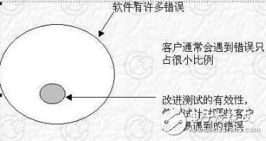
The basic idea of ​​the error guessing method: List all possible errors in the program and special cases that are prone to errors, and select test cases based on them. For example, many of the errors that are common in modules are listed during unit testing. These are the summaries of the mistakes that have been found in previous product tests. Also, the case where the input data and the output data are 0. Enter a table as a space or enter a table with only one line. These are all situations that are prone to errors. The examples in these cases can be selected as test cases.
Causal graphThe equivalence class partitioning method and the boundary value analysis method introduced above all focus on the input conditions, but do not consider the relationship between the input conditions, and combine with each other. Considering the combination of input conditions, some new situations may arise. But checking the combination of input conditions is not an easy task, even if all the input conditions are divided into equivalence classes, the combination between them is quite a lot. It is therefore necessary to consider designing a test case in a form suitable for describing a combination of multiple conditions and correspondingly generating multiple actions. This requires the use of causal maps (logical models).
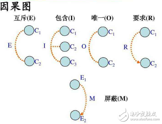
The causal map method ultimately produces a decision table. It is suitable for checking various combinations of program input conditions.
The basic steps for generating a test case using a causal graph :
(1) In the analysis software specification description, those are the reasons (ie, the equivalence class of input conditions or input conditions), those are the results (ie, output conditions), and each identifier and result is given an identifier.
(2) Analyze the semantics in the description of the software specification. Find the relationship between the cause and the result, the cause and the cause. Based on these relationships, draw a causal map.
(3) Due to grammatical or environmental constraints, there may be some combination of reasons and causes between the cause and the cause. To indicate these special circumstances, some symbols are used on the causal map to indicate constraints or constraints.
(4) Convert the causal map into a decision table.
(5) Design test cases by taking each column of the judgment table as a basis. The test cases generated from the causal map (local, combined) include TRUE and FALSE for all input data, and the number of test cases is minimized, and the number of test cases linearly increases with the number of input data. increase.
Judge table driving method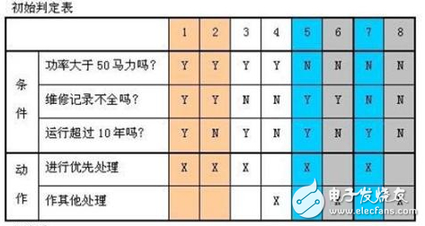
1. Conditional Pile: List all the conditions of the problem. The order of the listed conditions is generally considered to be unimportant.
2. Action Pile: List the possible actions that the problem stipulates. The order in which these operations are arranged is not constrained.
3. Condition item: List the value of the condition listed for it, and the true and false value in all possible cases.
4. Action item: List the value of the condition listed for it, and the true and false value in all possible cases.
5. Rules: The specific value of any combination of conditions and the corresponding operations to be performed. A column that runs through the condition item and the action item in the decision table is a rule. Obviously, how many sets of conditional values ​​are listed in the decision table, how many rules there are, and how many columns are available for conditional items and action items.
The basis and steps for establishing the judgment table:
1. Determine the number of rules. If there are N conditions, each condition has two values ​​(0, 1), so 2N rules.
2. List all conditional piles and action piles.
3. Fill in the condition item.
4. Fill in the action item. Develop an initial decision form.
5. Simplify. Combine similar rules or the same action.
Conditions suitable for use in the design of the specified decision table:
1. The rule description is given in the form of a decision table, or it can be easily converted into a decision table.
2. The sort order of the conditions does not affect the execution of those operations.
3. The order in which the rules are arranged does not affect the execution of those operations.
4. When the conditions of a certain rule have been met and the operations to be performed are determined, it is not necessary to check other rules.
5. If a rule is to perform multiple operations, the order in which these operations are executed does not matter.
Functional mapThe function diagram is used to visually represent the function description of the program, and the use case of the mechanical generation function diagram. The function diagram is a black box and white box hybrid use case design method.
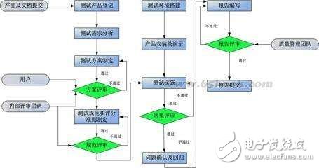
The function diagram consists of a state transition diagram and a logical function model:
1. The state transition diagram is used to represent the input data sequence and its corresponding input data. In the state transition diagram, there is input data and the current state determines the output data and subsequent states.
2. The logical function model is used to indicate the correspondence between input conditions and output conditions in the state. The logical function model is only suitable for describing static descriptions, and the output data is only determined by the input data. The test case consists of a series of states that pass through the test and a pair of conditions that must be met by the input/output data in each state.
The concepts and methods of logical coverage and path testing are used in the function diagram method. Designers are required to have a clear understanding of the logic structure of the program.
Generate use cases:
1. Generate a partial test case: In each state, generate a partial test case from the causal map. The local test library consists of a combination of cause values ​​(input data) and corresponding result values ​​(output data or state).
2. Test path generation: Use the above rules to generate a test path from the initial state to the last state.
3. Test Case Synthesis: A partial test case for each state in the composite test path and function diagram. The result is a sequence of states from the state to the last state, and the input data in each state is combined with the corresponding output data.
4. Synthetic algorithm for test cases: Conditional construction trees are used.
Orthogonal testSelect a proper amount of representative points from a large number of experimental data, and arrange the design method of the test reasonably.
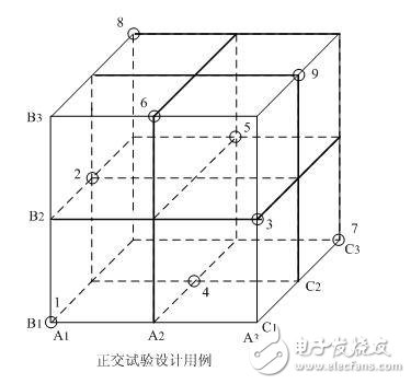
1. Extraction function description, construction factor--The state table refers to the condition that affects the experimental index as the factor, and the condition that affects the experimental factor is called the state of the factor. When using the orthogonal experimental design method to design test cases, firstly, according to the specification of the software to be tested, find out the operational objects and external factors that affect the function realization, and regard them as factors; and take the values ​​of each factor as the status. . Divide the functional requirements in the software requirements specification, and decompose and expand the overall and summary functional requirements into specific specific functional requirements with relative independence. In this way, all the factors in the tested software can be determined, and the basis for determining the weight of each factor can be provided. Determining factors and states is key to designing test cases. Therefore, it is required to determine the value as comprehensively and correctly as possible to ensure that the design of the test case is complete and effective.
2. Weighted screening, generation factor analysis table The selection of factors and states can be weighted according to their importance. The weight can be determined according to the size of each factor and state, the size of the frequency of occurrence, and the needs of the test.
3, using orthogonal table construction test data set The use of orthogonal experimental design method to design test cases, than the use of equivalence class division, boundary value analysis, causal maps and other methods have the following advantages: saving test work hours; control generated test cases Quantity; test cases have a certain coverage.
Comprehensive strategy for test methods:1. First perform an equivalence division, including the equivalent division of input and output conditions, and turn the infinite test into a finite test.
2. Use the boundary value analysis method.
3. Use error speculation to add some use cases.
4, against the program logic, check the logical coverage of the use case design, and strive to reach the coverage standard.
5. If there is a combination of input conditions in the program function description, the causal map and the decision table driving method can be selected.
6. For the parameter configuration software, use the orthogonal test method to select fewer combinations to achieve the best results.
7. The function diagram is a good method of use case design, and different test data is designed by the validity of the conditions in different periods. For the system with clear business process, the scenario method is used throughout the test process, and various test methods are used in the case.
Din Rail Connectors,Din Terminal Block,Din Rail Mount Terminal Block,Rail Terminal Block
Cixi Xinke Electronic Technology Co., Ltd. , https://www.cxxinke.com