At present, the radar altimeter mainly uses a pulse system and a continuous wave system. The pulse system radar altimeter includes a single pulse system, a chirped pulse system, a pseudo-random two-phase coded pulse system, and the like. Among them, the pulse system radar altimeter using modulation technology has better performance and anti-interference ability than the single-pulse radar altimeter. To further improve the performance of this system radar altimeter, the current solution can only be to increase the transmit power. However, high-power pulsed radar is easily detected and interfered by the enemy, which will reduce the safety of the radar altimeter to a certain extent.
The continuous wave chirp radar altimeter has better performance than the pulse altimeter. At present, there are two basic methods for generating chirp signals, namely, analog method and digital method. The analog method is a traditional method, which can be divided into active and passive methods. In the active method, there is a problem that the carrier of the chirp signal is out of phase with the reference signal, and the long-term and short-term stability of the oscillator is poor, the oscillation frequency may drift with temperature, and the phase noise performance is also poor. The method of generating a chirp signal by the passive method is difficult to achieve a large time width and bandwidth.
Direct digital frequency synthesis is a digital method of generating a chirp signal. Techniques for generating chirp signals and other frequency synthesizing signals in this way have received increasing attention and have been widely used. Through the single-chip control, the direct digital frequency synthesis technology can generate output waveforms with precise frequency, amplitude and phase control. WwW.11665.coM This paper uses the direct digital frequency synthesis chip ad9854 produced by adi company as the core to generate the chirp signal.
2.ad9854 chip introduction and characteristicsThe ad9854 digital synthesizer is a highly integrated device that uses advanced dds technology to integrate two high-speed, high-performance quadrature d/a converters to output i and q two-way composite signals through digital programming. Driven by a high-stability clock, the ad9854 produces a highly stable frequency, phase, and amplitude programmable sine and cosine signals. The ad9854 includes a 48-bit phase accumulator, a programmable clock multiplier, an inverse sinc filter, two 12-bit 300mhz dacs, a high-speed analog comparator, and interface logic. The ad9854's 300m system clock is available from a lower external reference clock through 4x and 20x programmable control circuitry. The direct 300m clock can also be input via single or differential inputs. The ad9854 also has a conventional fsk for single-pin input and an improved slope fsk output. The ad9854 uses the coms process to provide powerful features in a single 3.3V supply.

3.1 System hardware structure
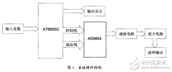
The whole linear frequency modulation circuit supply voltage is 5v and 3.3v, and the system hardware structure is shown in Figure 1. In the figure, the single chip is used as the control core, and the frequency range and frequency step value are set by the button, and the set value is displayed through the digital tube. The MCU connects with the ad9854 through the control line and the data line, and issues the corresponding control word to update the frequency. When the signal output by ad9854 is high, the signal noise is very large, which affects the signal quality. After the signal frequency increases, the peak value will further decrease. To do this, it is necessary to filter after the signal is sent by the ad9854. After filtering, the circuit is amplified, and finally the output signal is displayed by the oscilloscope.

3.2 system filter amplifier circuit
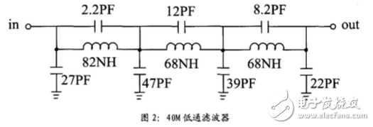
The signal output by ad9854 is low frequency, generally less than 5m, the signal output is less interfered, the signal frequency rises. If there is no filter circuit, the output signal frequency is distorted. The higher the frequency, the more severe the distortion. In order to eliminate this scene, the output signal must be filtered. The output frequency of the signal source is set within 40m. Therefore, the filter circuit is designed to be low-pass below 40m, and the low-pass filter with particularly high frequency requires a particularly small inductance value. In the form of a patch. The specific circuit is shown in Figure 2.

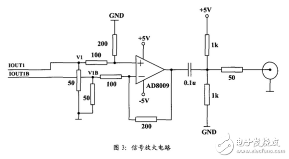
The ad9854 chip supply voltage is 3.3v. In addition to the need for an external filter circuit, an amplifier circuit is required. As the frequency increases, the signal output voltage will decrease. The design of the amplifier circuit will use ad8009 as the core amplifier chip. The internal dada of ad9854 is the current type output, the iout and ioutb complementary current output, and the 50Ω resistor is not connected to convert the output current into The output voltages v1 and v1b, v1 are amplified in the same direction, and v1b is amplified in the direction. According to the superposition principle, the output is proportional to the difference between the two voltages. The ad9854 has two quadrature output signals, so the amplifier circuit requires two groups. One set of amplification circuits is shown in the figure. The specific circuit is shown in Figure 3.

The software part is designed to make the system run according to the design requirements through the program design related registers. The main part of the system is to write the two 48-bit frequency control words of ad9840 into the frequency control register of ad9854 through the single-chip microcomputer. The sweep frequency signal needs to be set. Start scan frequency, end scan frequency, scan step frequency, scan step speed. The system design inputs the relevant values ​​through the keyboard mode and displays the relevant values ​​through the led. The ad9854 has two configurations, serial and parallel. This article uses parallel write mode.
Based on the introduction of dds chip ad9854, this paper designs the hardware structure diagram of linear frequency modulation signal generator by using parallel control method of single chip microcomputer, and designs the filter circuit and amplifier circuit in detail. Finally, the software design flow chart is given. The author passes the test of the actual circuit, the design scheme is correct and feasible, the frequency control is simple, flexible, and can be visually displayed in the digital tube, which has a good application prospect.
>>>>>>ad9854 driver design free download
The Ideal RJ45 Cat6 Modular Plugs (25-Pack) support speeds associated with Category 6-cable. These plugs offer gold contacts and are suitable for solid or stranded 22 - 23 AWG conductors. Refer to the instructions sheet for terminating the plugs.
- Designed for use with Cat6 universal twisted pair wire
- 50-micron gold contacts
- Suitable for solid or stranded 22 - 23 AWG conductors
- 3-piece, 8-position/8-contact design provides easy installation and optimal performance
- Crimps with a standard RJ-45 crimp die
CAT6 Modular Plug, modular cat 6, 8P8C STP Modular Plug, RJ45 Modular Plug
NINGBO UONICORE ELECTRONICS CO., LTD , https://www.uniconmelectronics.com