Instrument calibration method for vibration and shock sensors
1
, instrument calibration content and scope of application
2
GB/T 2298
GB/T 13823.1
3.
GB/T 2298
. Magnetic sensitivity definitionGB/T 13823.1
First 4.3.6
Article.
4
4.1
1
Shown: bracket coil sensor sensor output test platform air cushion isolator
a
b
(
That is, at the center of the two coils)
.
c
0.01T
Frequency is50Hz
The alternating magnetic field. Magnetic field unevenness must not exceed the space in which the sensor is installed±10
%.
d
50
Double, and at the same time, take vibration isolation measures to make the signal-to-noise ratio greater than the test10dB
.
e
4
2
Low noise amplifier±2
%.
4
3
AC voltmeter±1
%
4.4
±5
%
4.5
20±5
degree
5.
5.1
5.2
0.01T
.
5
3
Test procedure
a.
b.
c.
a
~b
The steps until the sensor's output value in the magnetic field is found.
6.
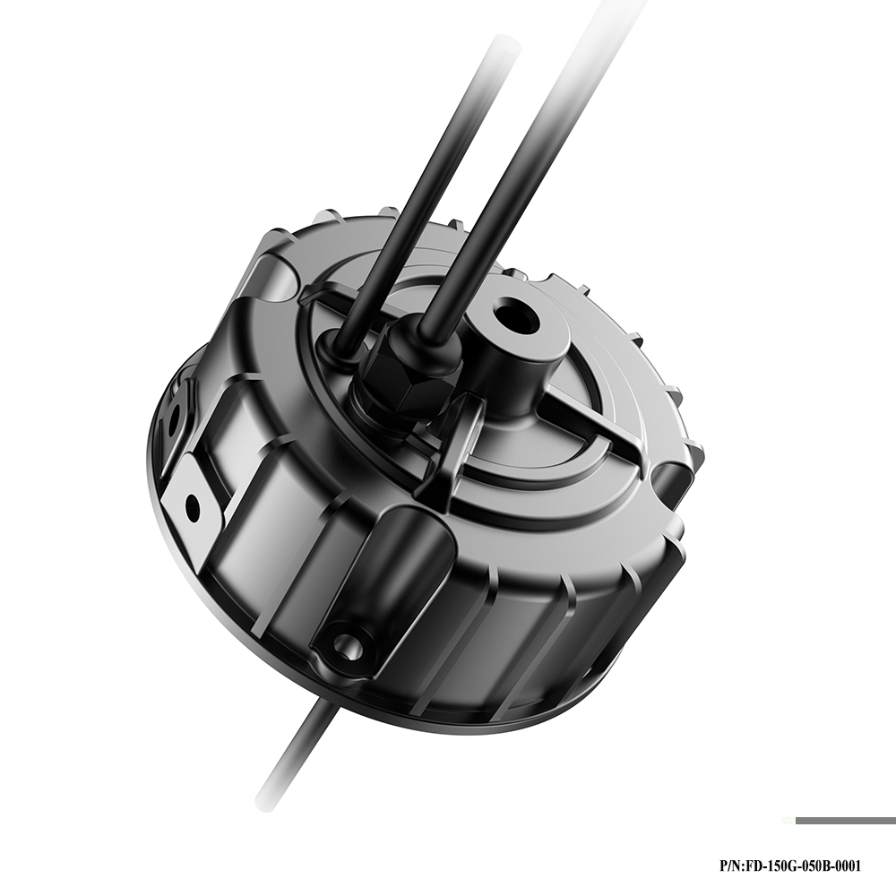
High Bay Light Led Driver
Constant current LED driver, UL dimmable transformer, With global manufacturing standards and various certifications including CE, UL and FCC, our lighting products are sold in domestic market and are exported to various international markets including US, UK, France, Germany, Australia, Africa, Korea etc. We offer a wide range of LED lighting solutions which includes LED Linear Lighting or System, , LED Lams, LED High bay lights etc. Maximize beauty of your workplace with our beautiful Warehouse Lighting, Workshop Lighting, Supermarket Lighting and Factory lighting solutions.
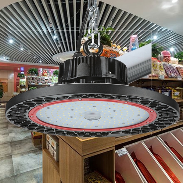
Application: Specifically for high bay light,High Power Led Driver above 100W,normal for outdoor for waterproof, AC100-277V, 0-10V/PWM/RX dimming,short circuit protection,class 2 satety output design, passed the UL/FCC/TUV/RCM/CB/CE Certified. Europe and North America market.
Parameter:
Input voltage: 100-277vac
output voltage: 25-143vdc
current: 100mA-8000mA.
Power factor: >0.9
IP degree: IP65
Dimming:0-10V / PWM / RX / DALI.
>=50000hours, 3-5 years warranty.
certificate: UL CE FCC TUV SAA ect.


FAQ:
Question 1:Are you a factory or a trading company?
Answer: We are a factory.
Question 2: Payment term?
Answer: 30% TT deposit + 70% TT before shipment,50% TT deposit + 50% LC balance, Flexible payment
can be negotiated.
Question 3: What's the main business of Fahold?
Answer: Fahold focused on LED controllers and dimmers from 2010. We have 28 engineers who dedicated themselves to researching and developing LED controlling and dimming system.
Question 4: What Fahold will do if we have problems after receiving your products?
Answer: Our products have been strictly inspected before shipping. Once you receive the products you are not satisfied, please feel free to contact us in time, we will do our best to solve any of your problems with our good after-sale service.
Led Driver Dimmable,UL Dimmable Transformer,Constant Current Led Driver,Saucer Type LED Driver,how to attach led light strips
ShenZhen Fahold Electronic Limited , https://www.fahold.net